Nortel Meridian 1 Option 11: NTAK04 AC/DC
PSU Conversion to NTAK05 DC PSU
Joe Zatarski
Shadytel
May 1, 2021
This page is formatted a bit differently from the rest of the site since this document was originally written in LaTeX.
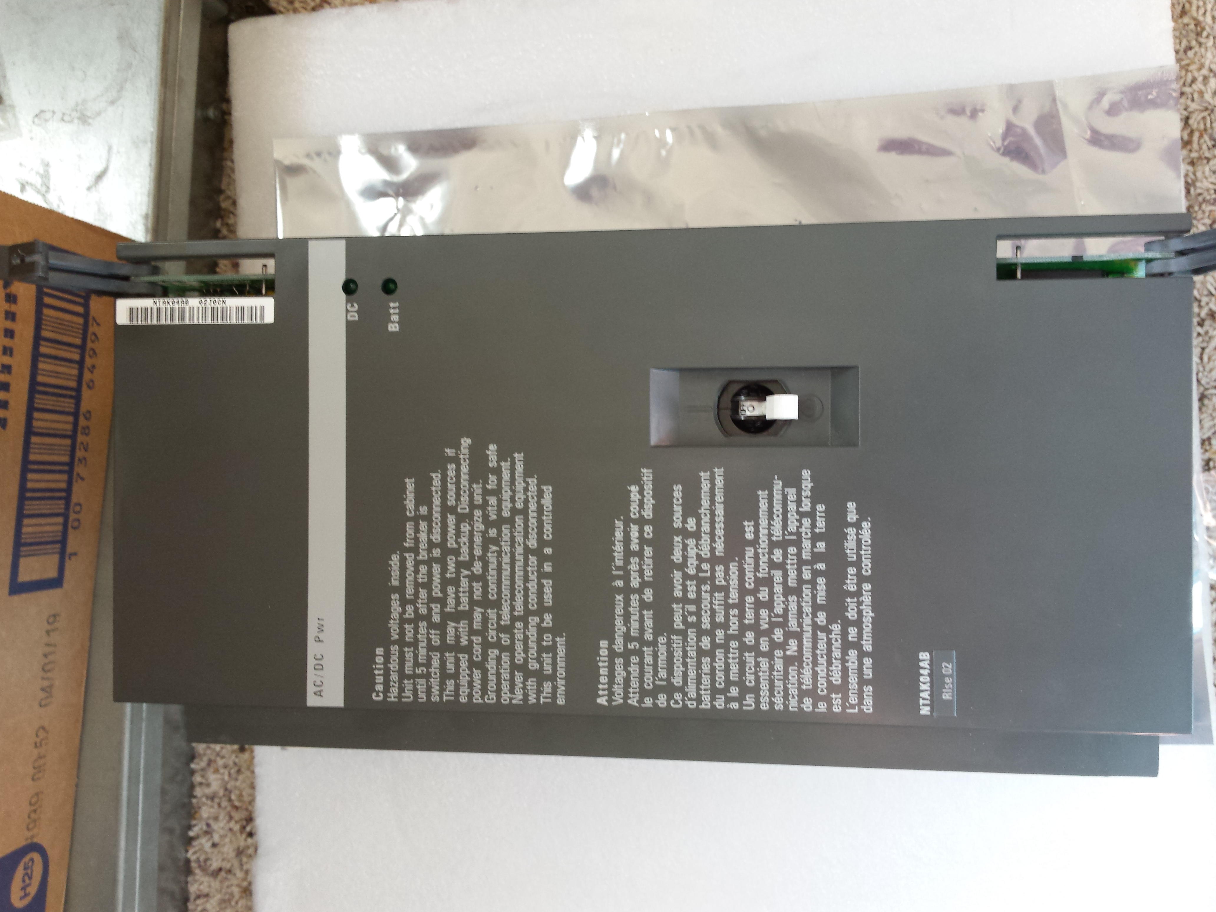
Nortel Meridian 1 Option 11: NTAK04 AC/DC
PSU Conversion to NTAK05 DC PSU
Joe Zatarski
Shadytel
May 1, 2021
Abstract
MOST Nortel Meridian 1 Option 11 PBXes (herein referred to as an ’Option 11’) sold in the North American market were supplied with the NTAK04 AC/DC power supply, making the NTAK05 DC power supply difficult to obtain. At the time of writing, no DC power supplies could be found at hobbyist-friendly prices in North America on the gray market. While there were some power supplies available shipping from Israel, the PSU would have cost more than a complete Option 11 PBX.
For most hobbyists, the NTAK04 will meet their needs. However, for those who have an existing -48VDC system for powering other equipment, the NTAK05 may be convenient to consolidate battery backup equipment, or improve power efficiency by using high efficiency rectifiers for the DC system. Unfortunately, the NTAK04 cannot be powered up on DC alone, requiring AC power for the initial startup. For these reasons, a hobbyist may wish to convert their NTAK04 into an NTAK05.
Most of what is required to build an NTAK05 is already present inside the NTAK04. The additional parts required are listed below.
Additionally, some basic tools are required:
Furthermore, it is good practice to have an ESD safe workspace setup and use proper grounding techniques. Refer to Nortel documentation for more information on ESD precautions.
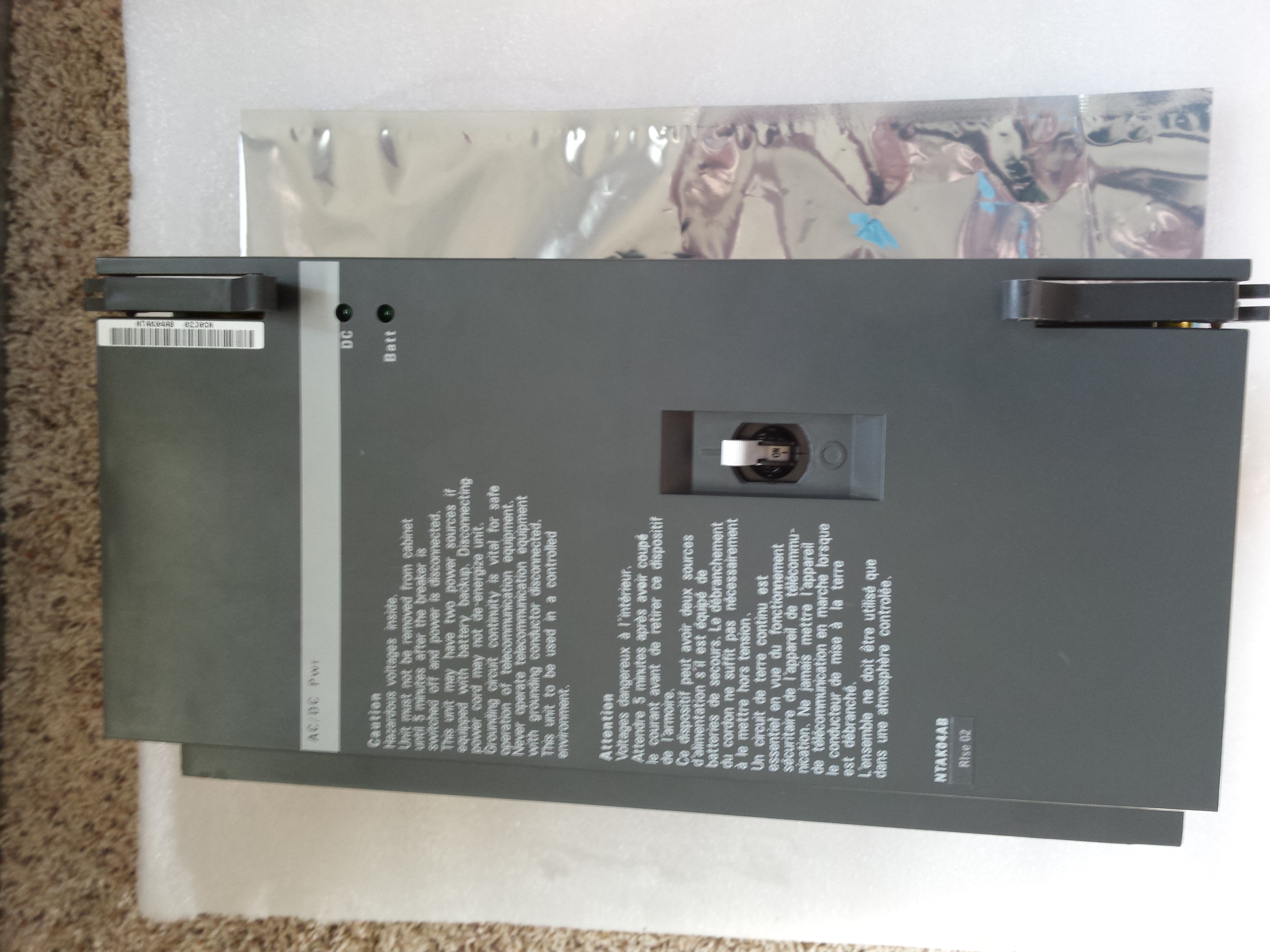
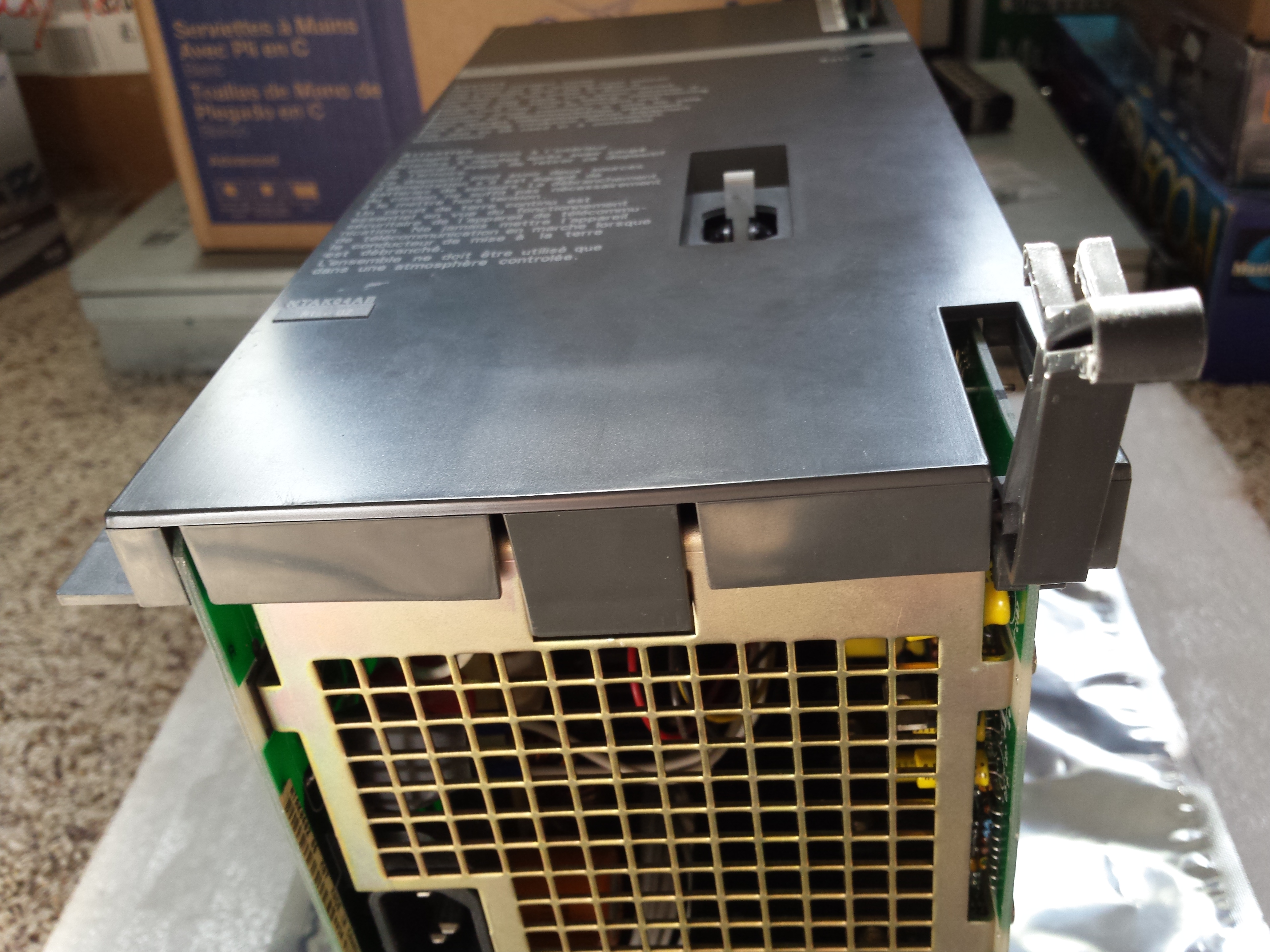
Place the NTAK04 on a clean, flat workspace. Remove the plastic front panel by releasing the two clips at the top and bottom. Refer to figure 2. Note that the card handles must be placed in the out position to remove the front panel.
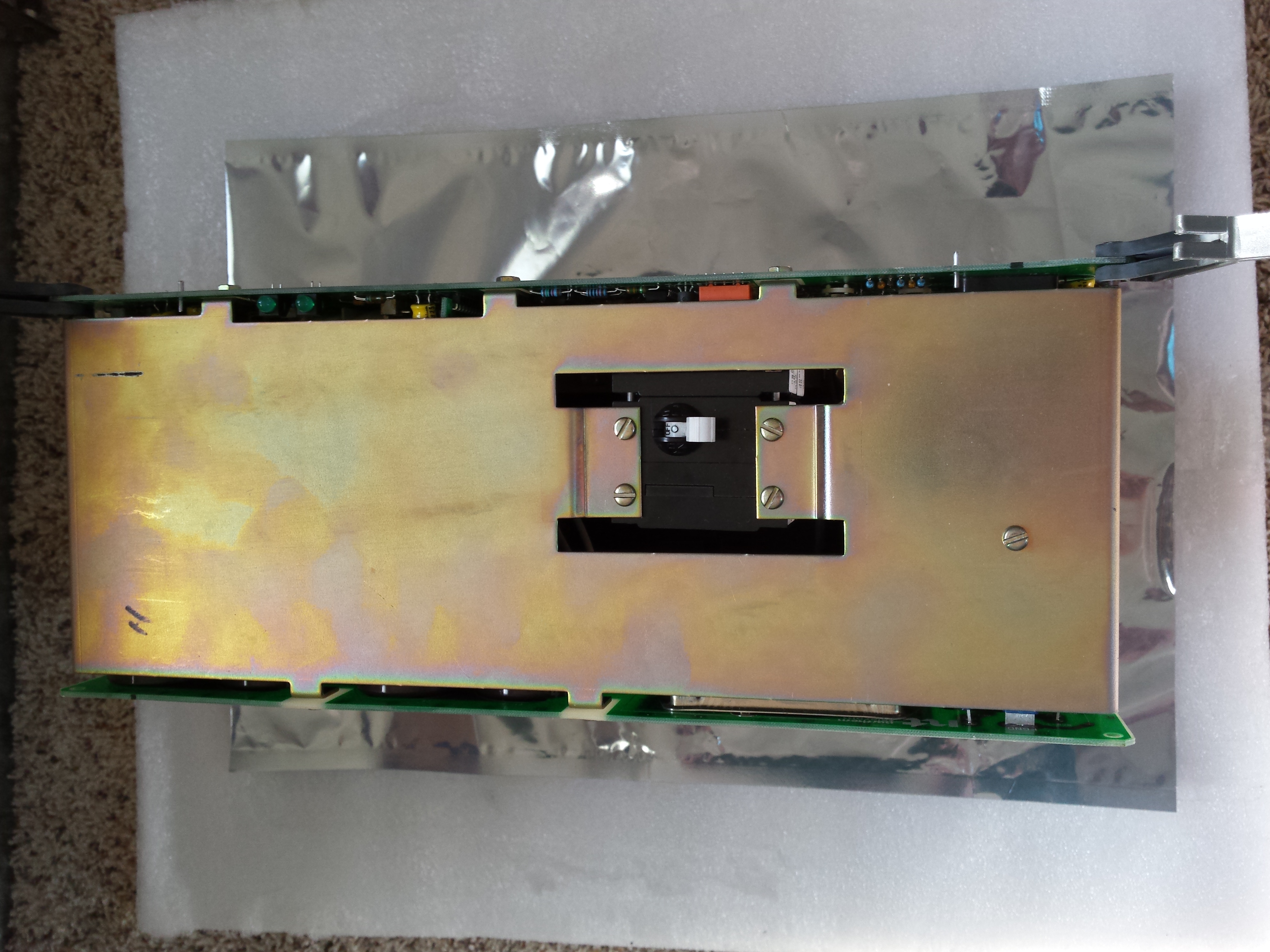
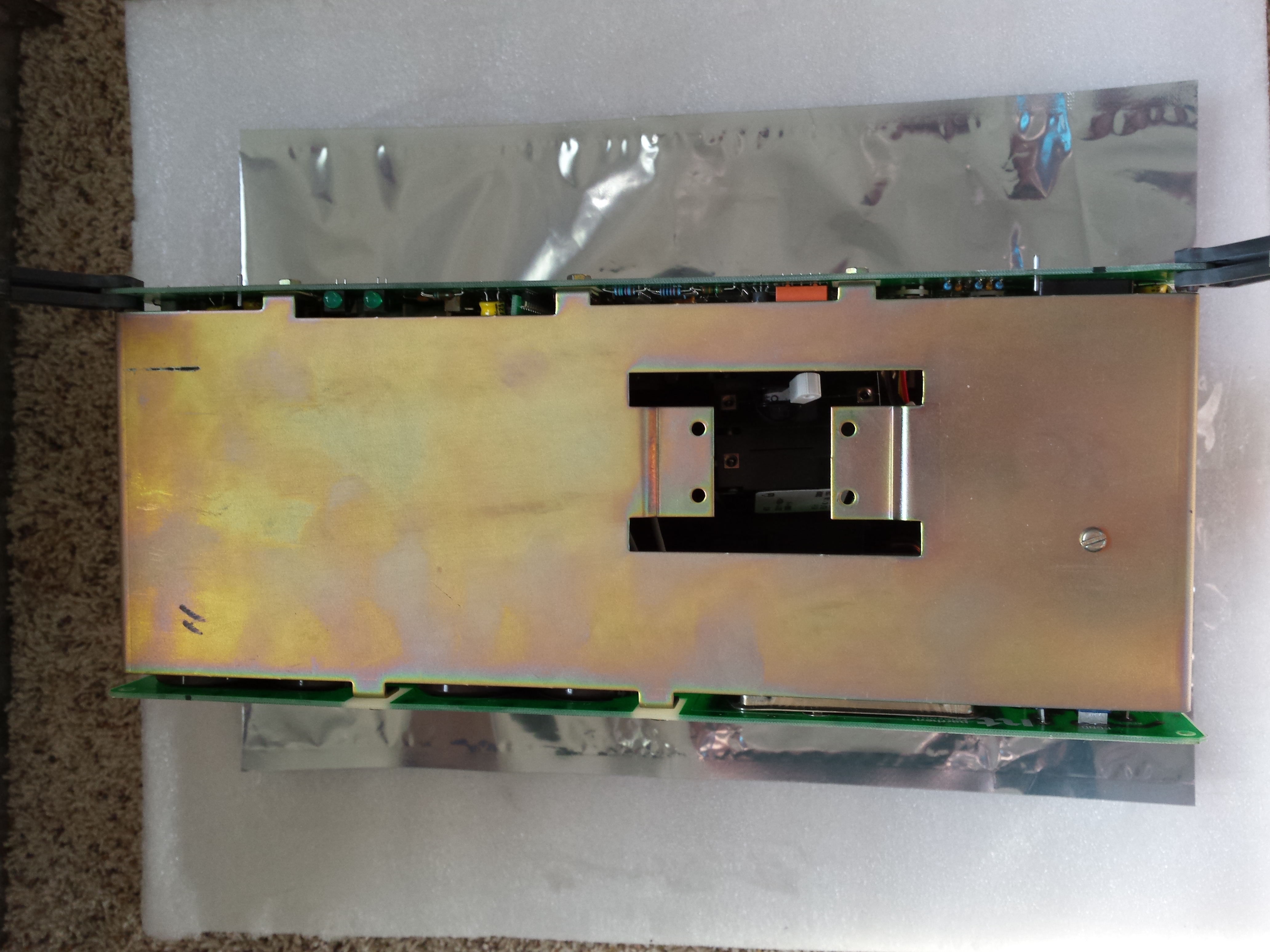
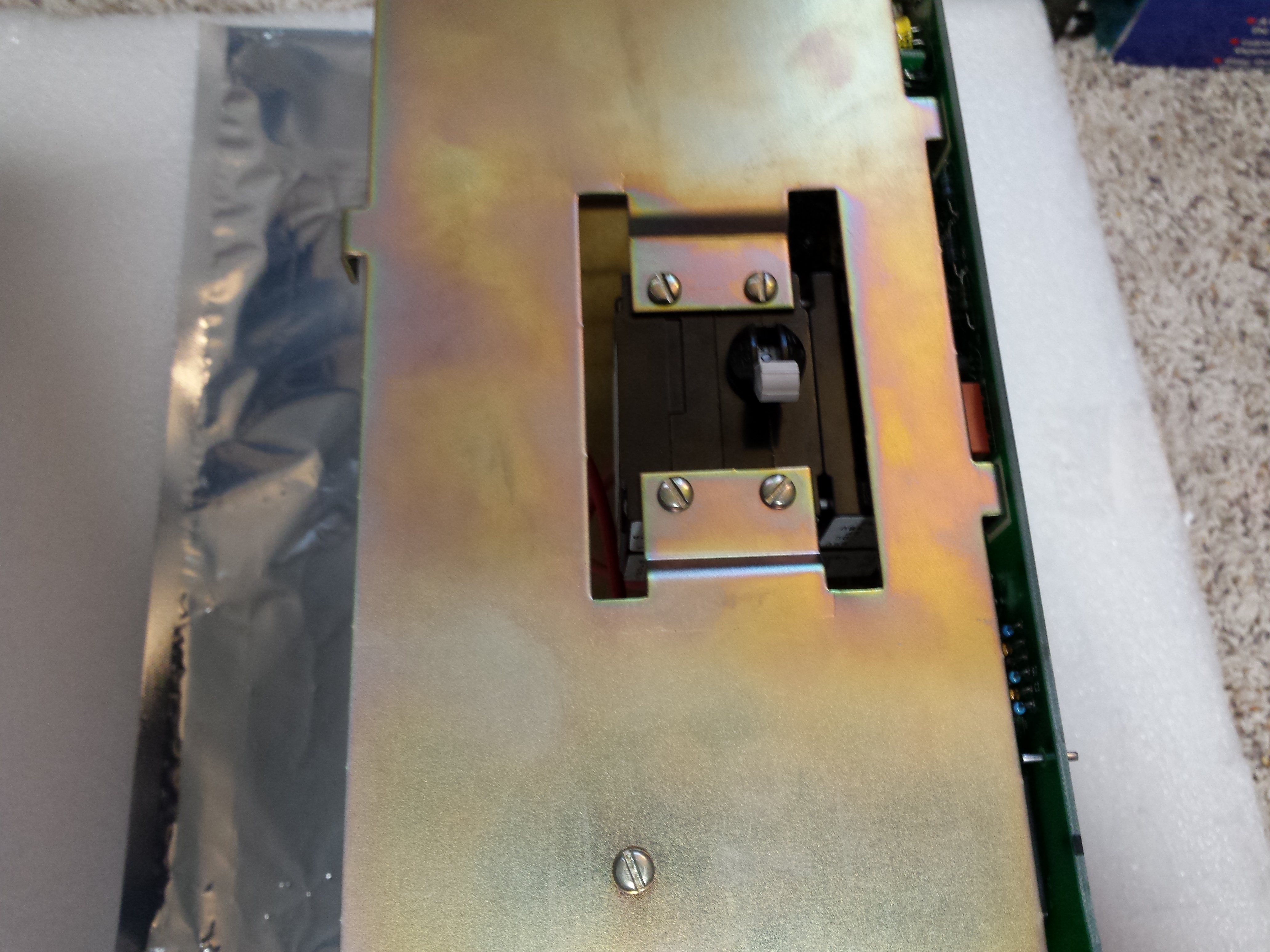
Next, remove the 4 flat blade screws holding in the circuit breaker assembly. Refer to figures 3 and 4.
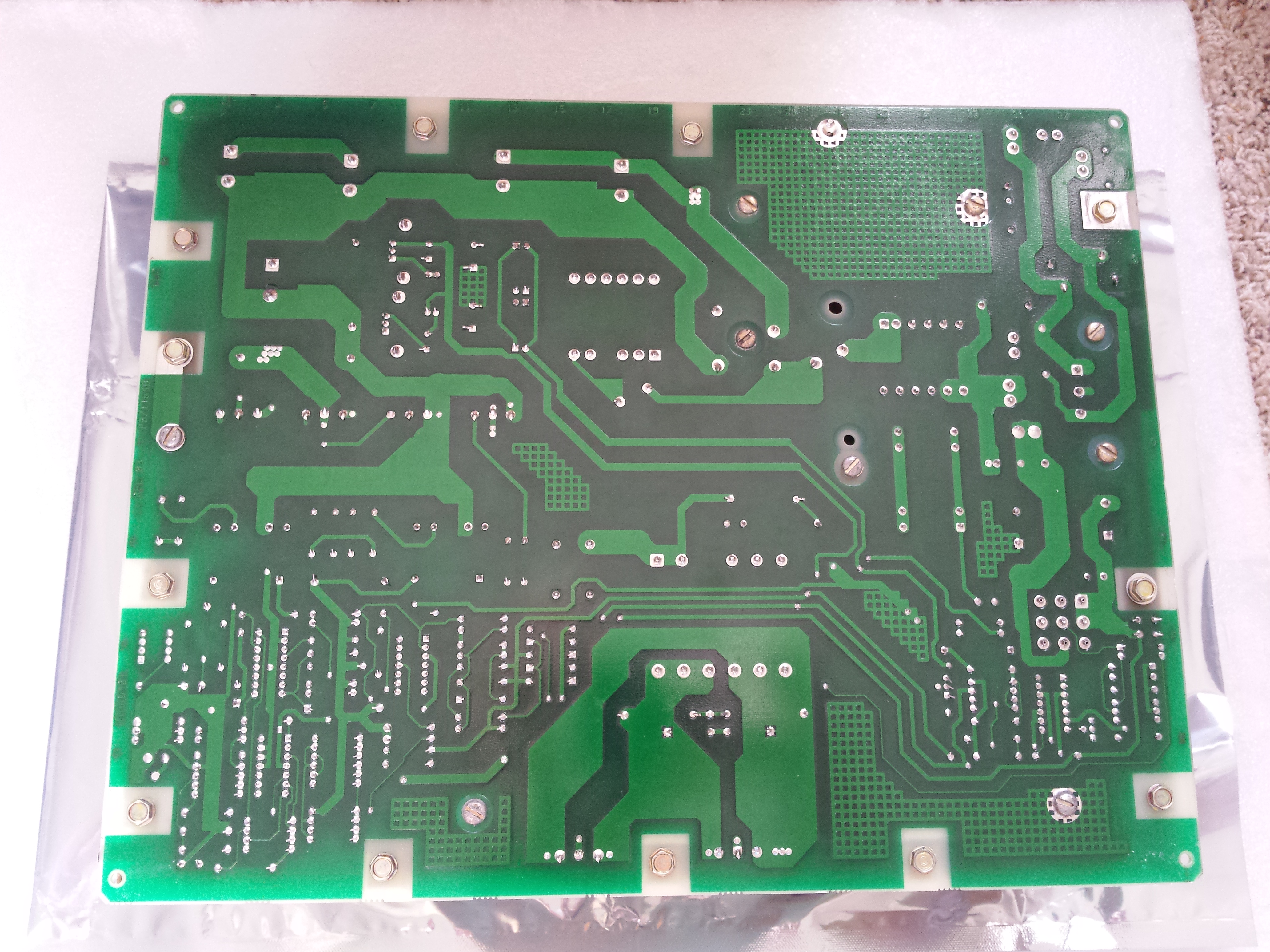
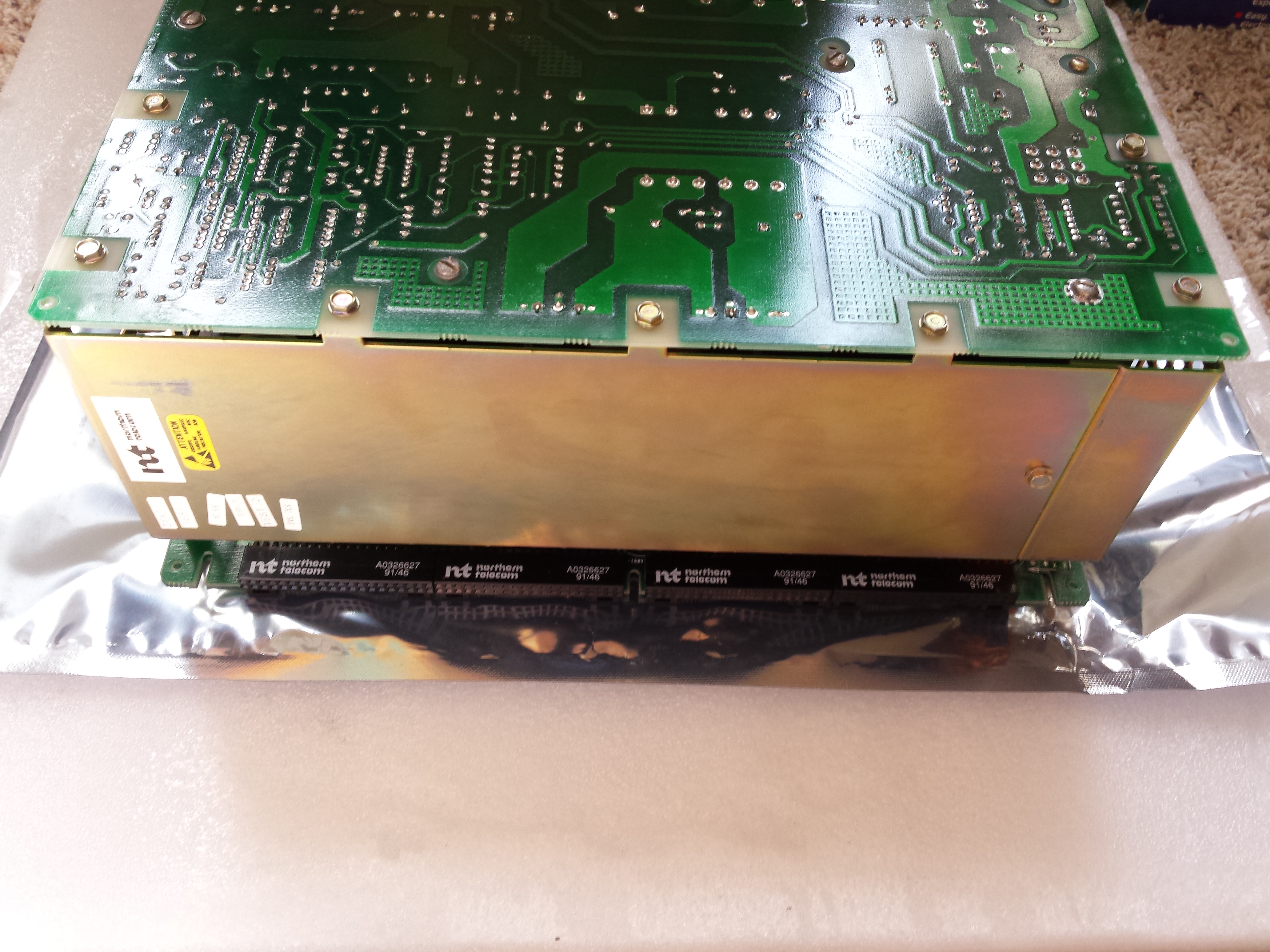
Reposition the power supply with the AC board up, and the DC board on the work surface. The DC board is identified by the backup battery and backplane connectors which are located on it. Refer to figures 5 and 6. Remove the 12 1/4-inch hex head screws located around the perimeter of the AC board which secure the board to the chassis. Do not remove the flat blade screws which hold various components to the board. Note that some screws have lock washers on them. If conversion back to AC is ever required, note where the lock washers go.
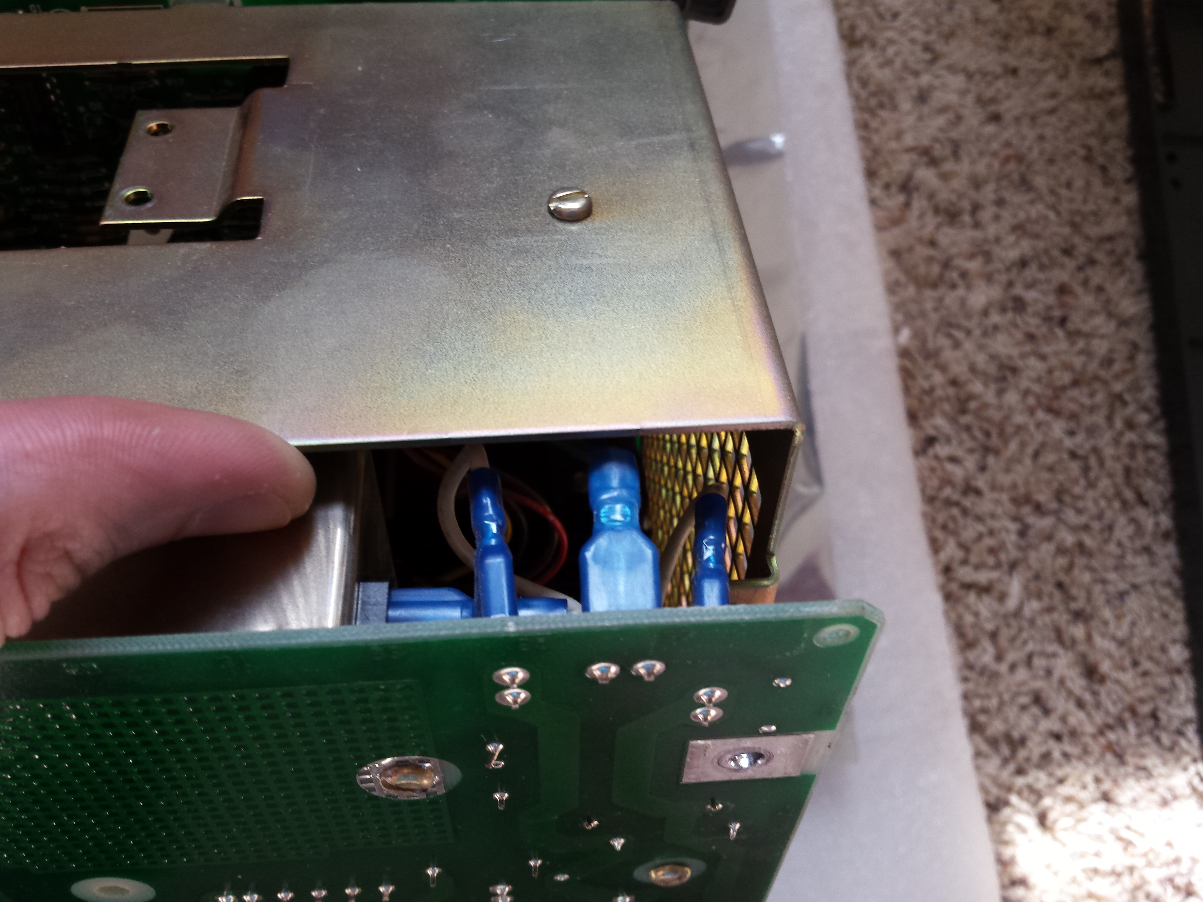
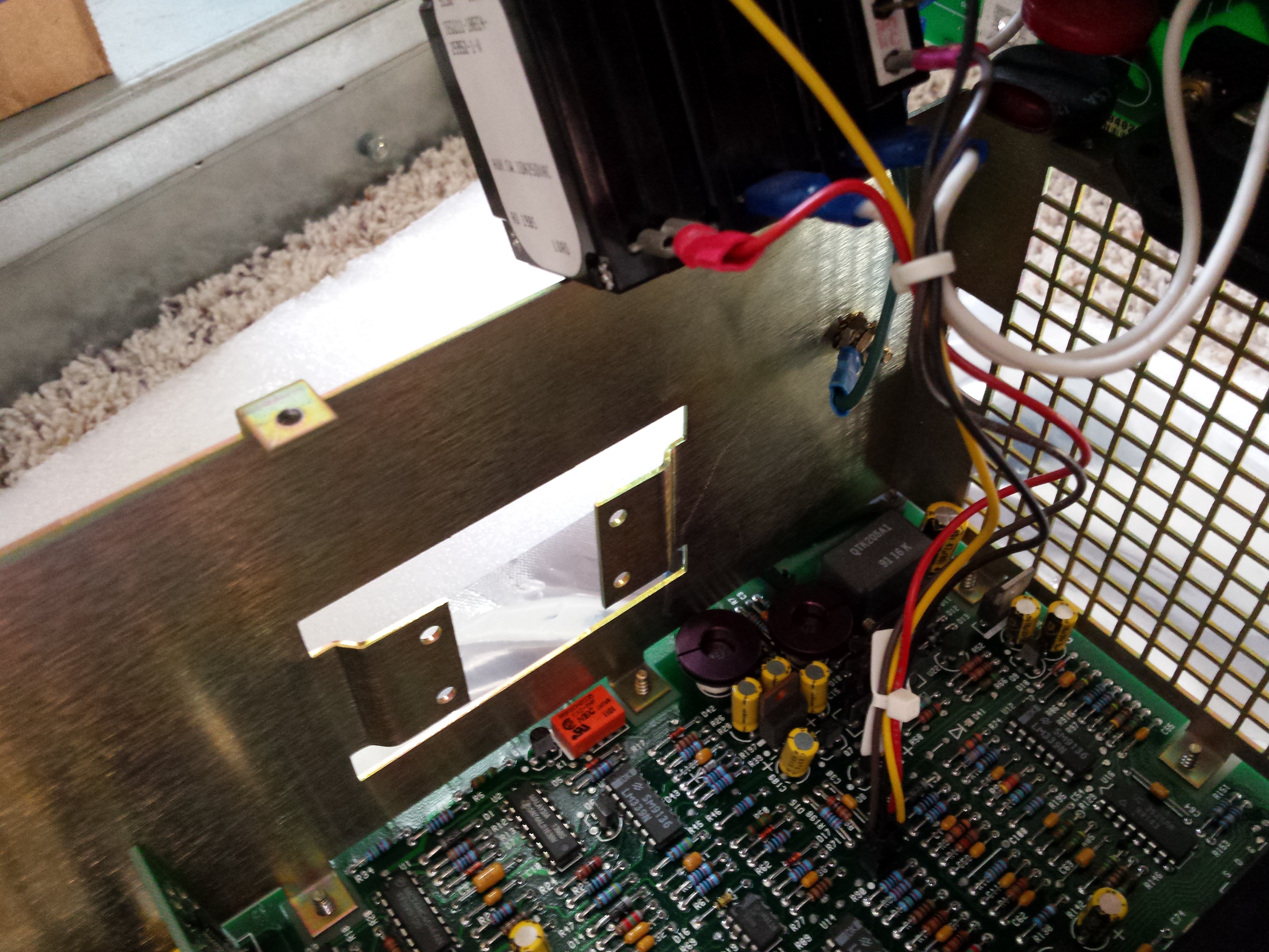
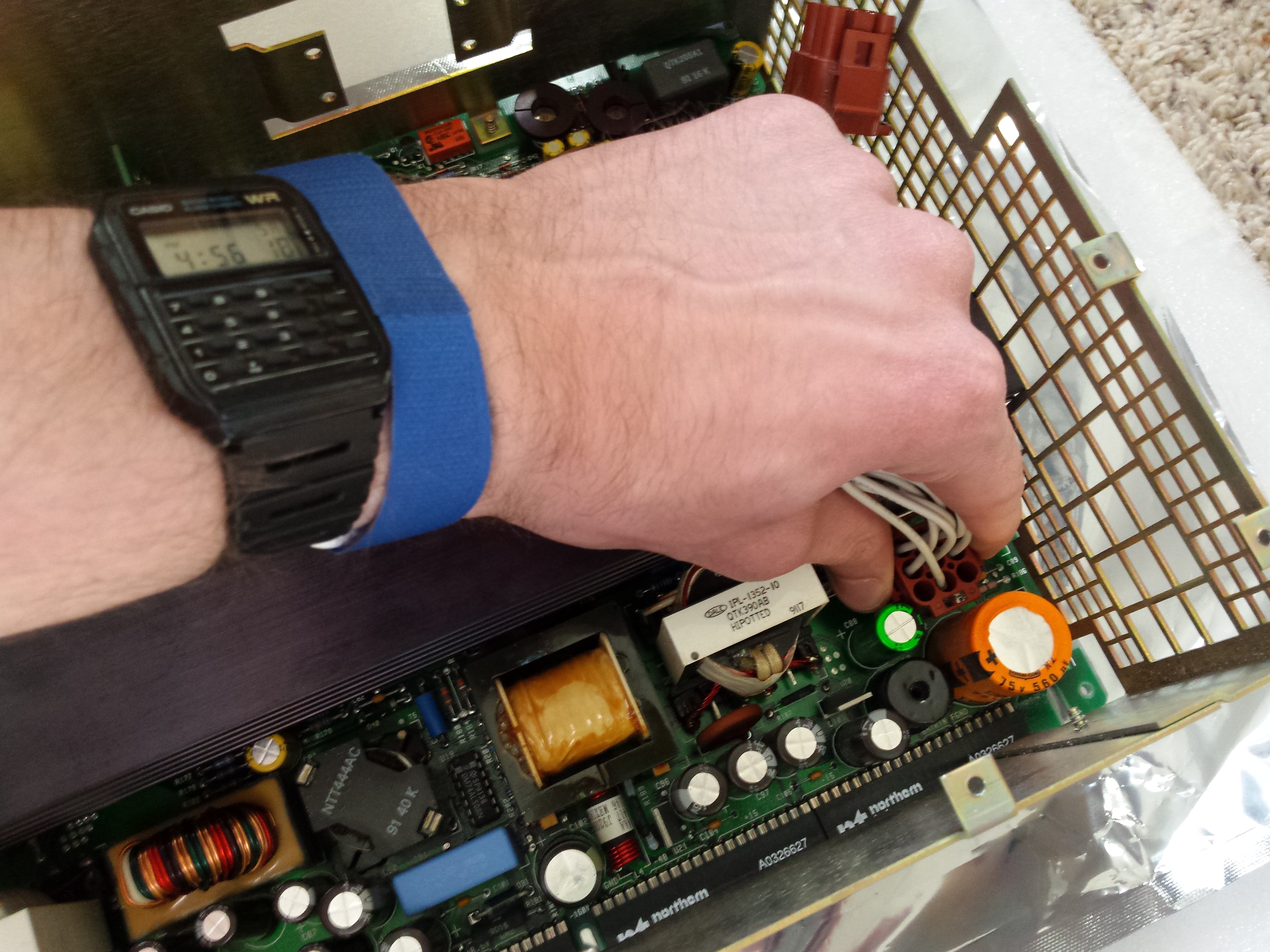
Before removing the AC board, some connectors will need to be disconnected. Remove the ground pigtail which is connected to the AC board near the bottom of the front of the power supply with a faston terminal. Refer to figure 7.
Disconnect the 9 pin cable from the AC board which connects it to the DC board. Refer to figure 8
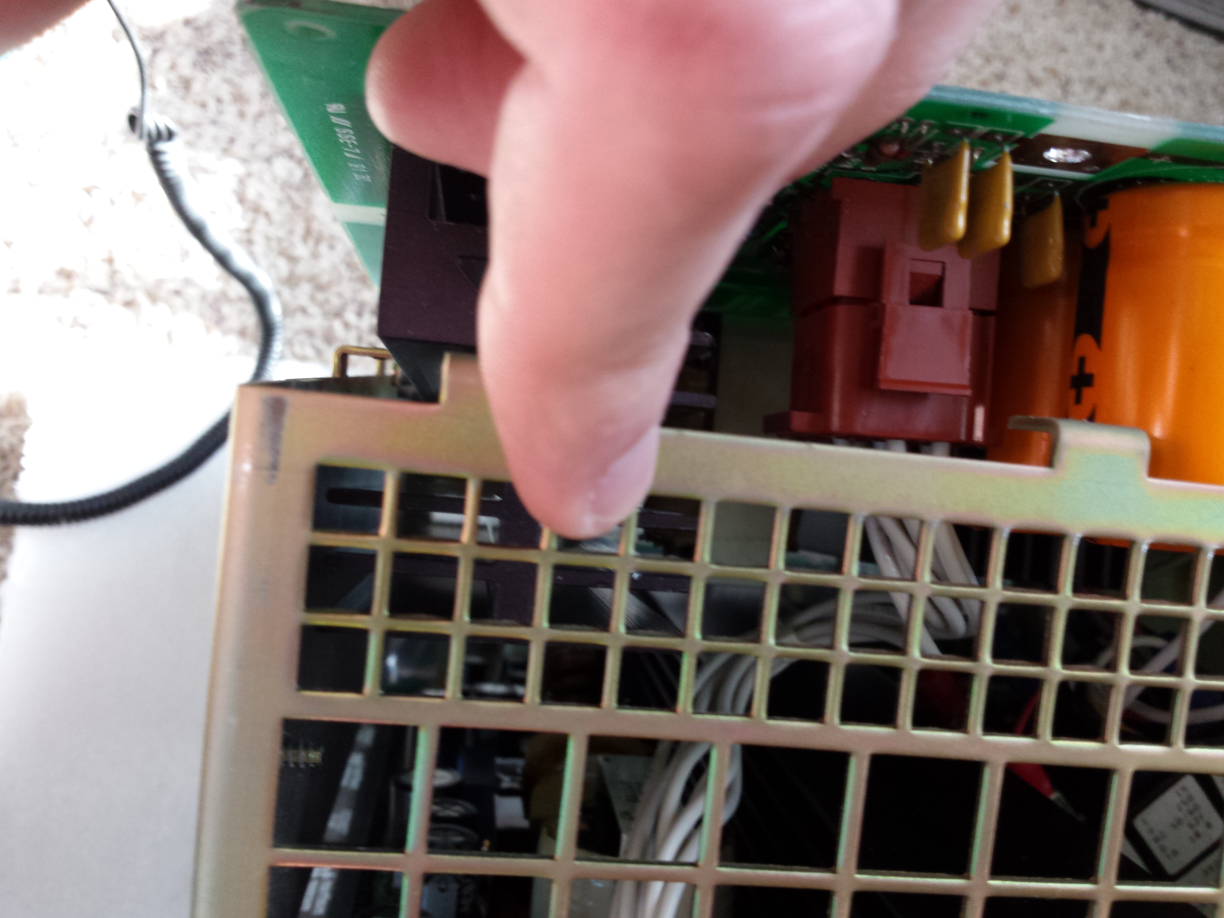
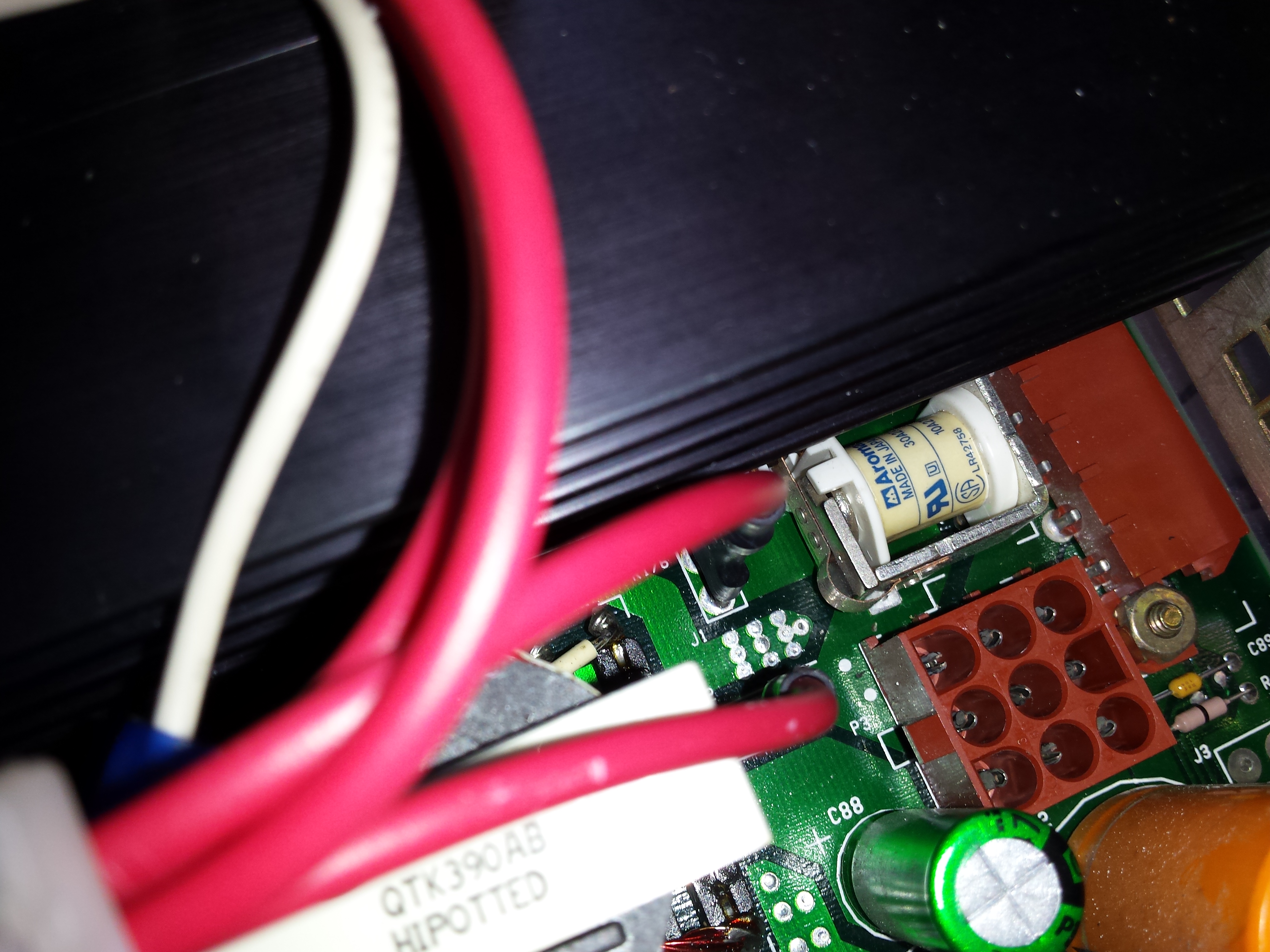
The breaker assembly will still be attached to the AC board by faston wires, as well as the DC board by a small 6 pin connector (refer to figure 9). The 6 pin connector has no locking mechanism, and should pull off easily if the AC board is lifted straight up and out of the chassis at this time. Remove the AC board, set the DC board/chassis assembly aside, and set the AC board in the workspace.
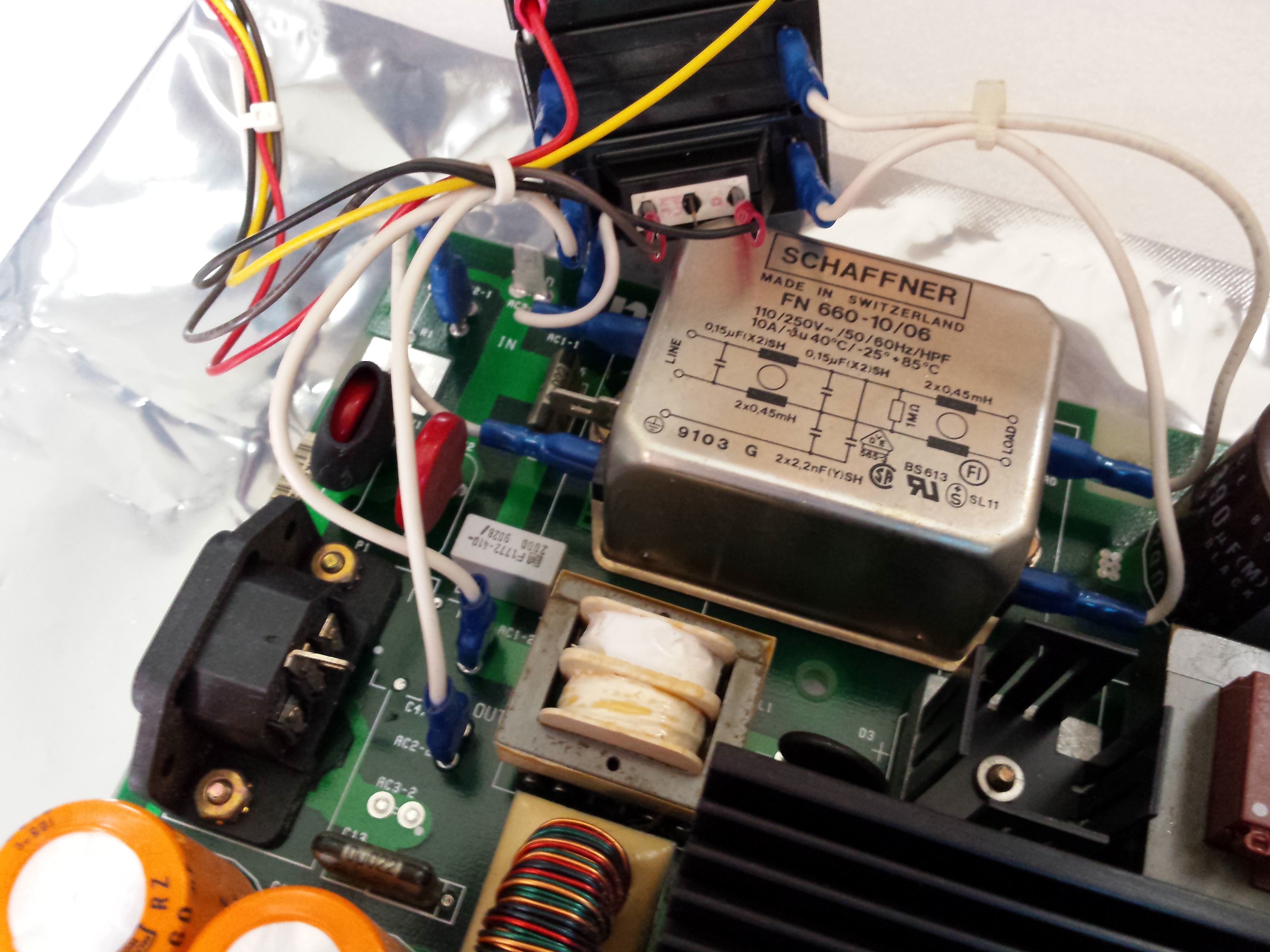
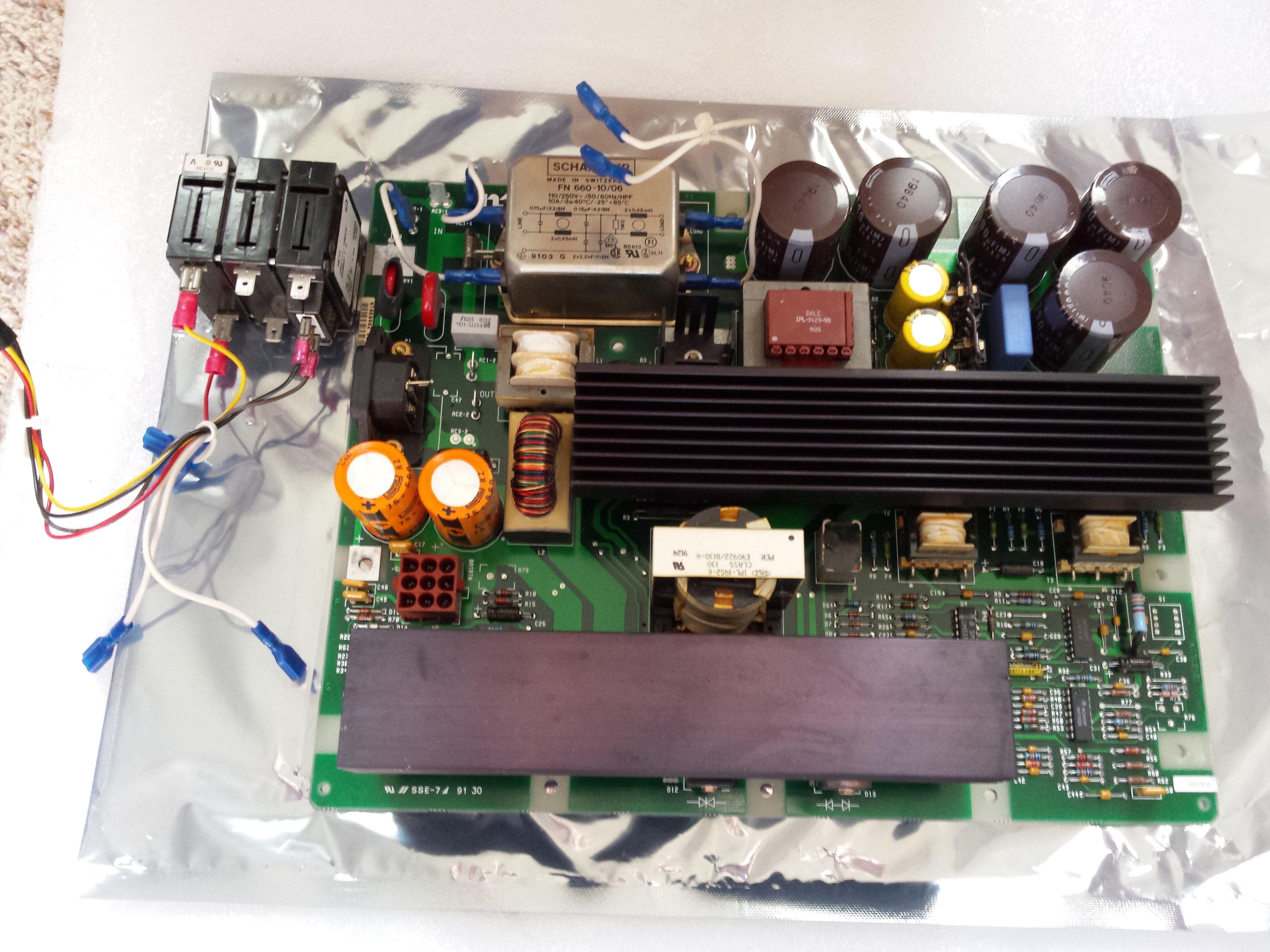
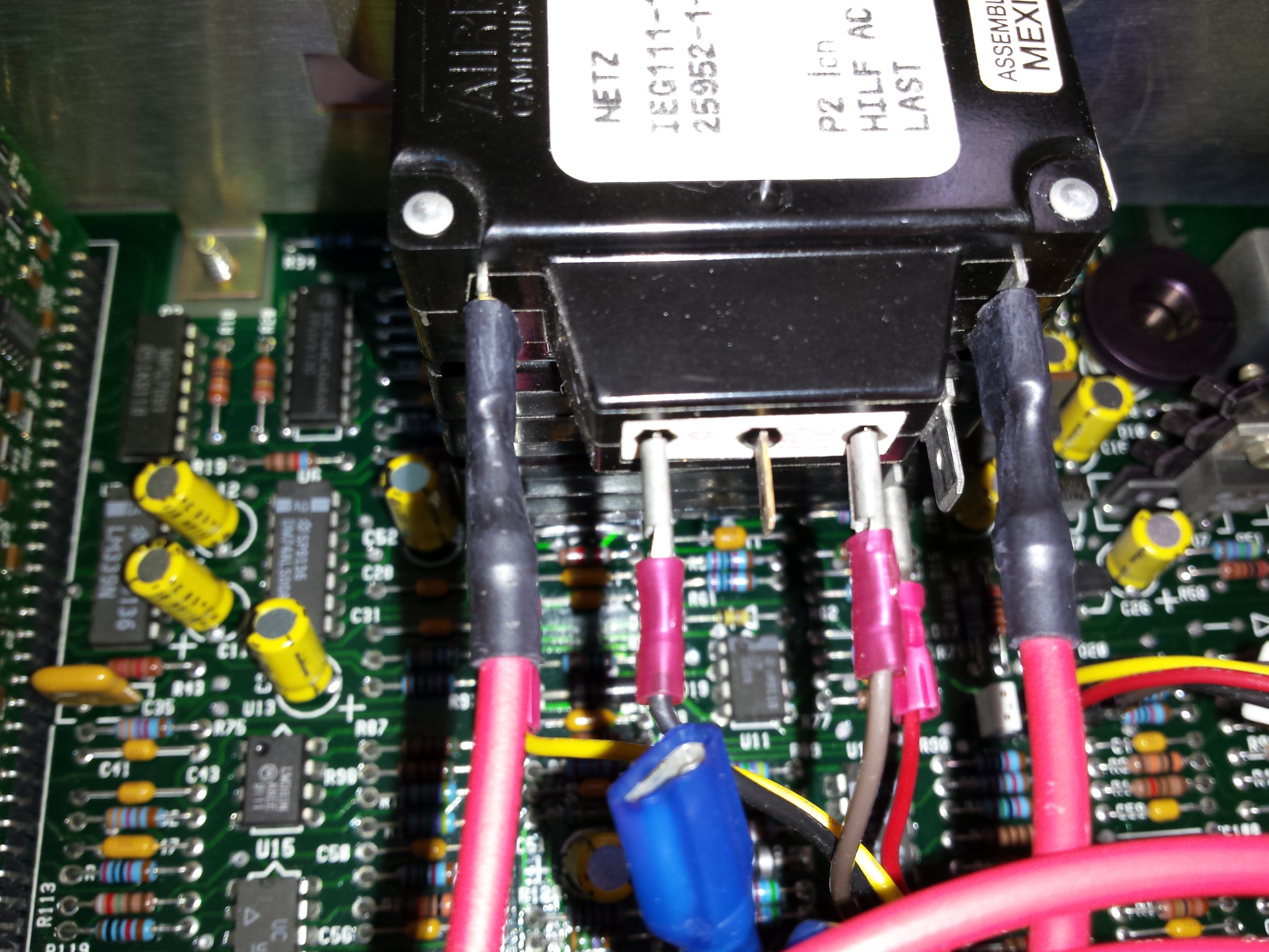
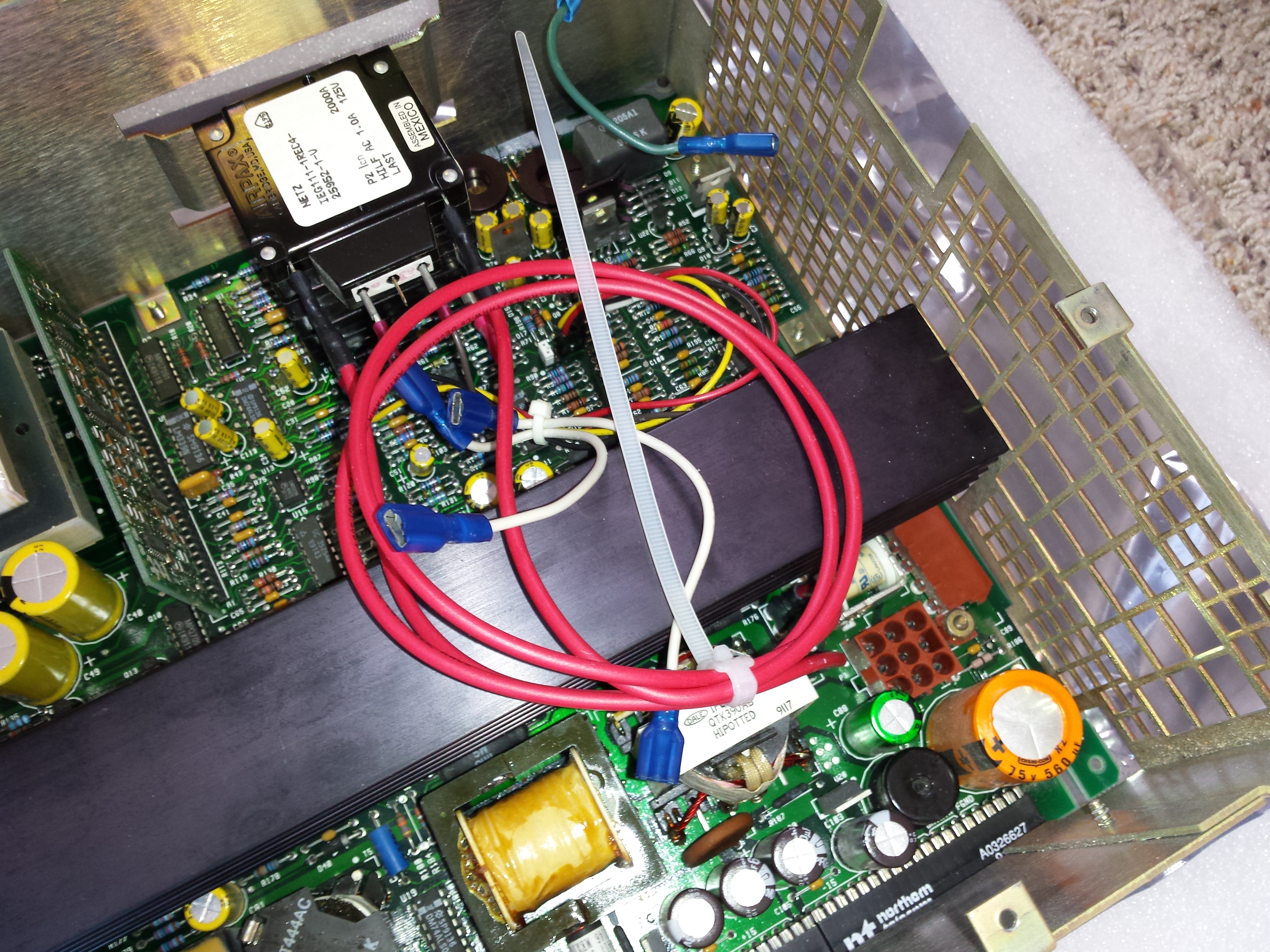
The breaker assembly is attached to the AC board by 4 faston wires. AC1-2 goes to one pole of the breaker assembly, through the line filter, to AC1-1. Similarly, AC2-2 goes to the other pole of the breaker assembly, through the other side of the line filter, to AC2-1. Remove all 4 of these AC wires from the breaker assembly. Additionally, either cut the cable tie securing the short faston cables to the 4 other wires, or remove the faston cables from the AC1-2 and AC2-2 terminals on the AC board. Refer to figures 10 and 11.
Set the AC board aside and move the DC board and chassis to the workspace. Reinstall the breaker assembly into chassis using the 4 flat blade screws removed earlier. Refer to figure 12.
Remove the 9 pin cable from the DC board. Refer to figure 13.
On the DC PSU, two of the wires going to the 6 pin connector are still used for tripping the breaker using an auxiliary coil. However, the other two wires are for a trip-closed contact set only used in the AC supply to ensure the power supply shuts off if it is running on DC and the breaker is switched off. However, the DC power supply does not use this feature and needs those two pins jumpered.
The 6 pin connector is keyed to only fit header P1 in the proper orientation. The connector needs to be rotated 180 degrees and placed on the connector so that only the two pins going to the auxiliary trip coil are connected to the rightmost two pins. Then a .1 inch pitch jumper needs to be placed between the leftmost two pins. On the authors PSU (NTAK04AB Rlse 02), the two wires for the auxiliary trip coil were red and yellow, while the trip-closed contacts from the breaker assembly were the black and brown wires.
To reiterate, the black and brown wires will not be connected in the DC PSU, but the red and yellow should still be connected (polarity will be flipped, but the auxiliary coil is not sensitive to polarity). Refer to figures 14 and 15.
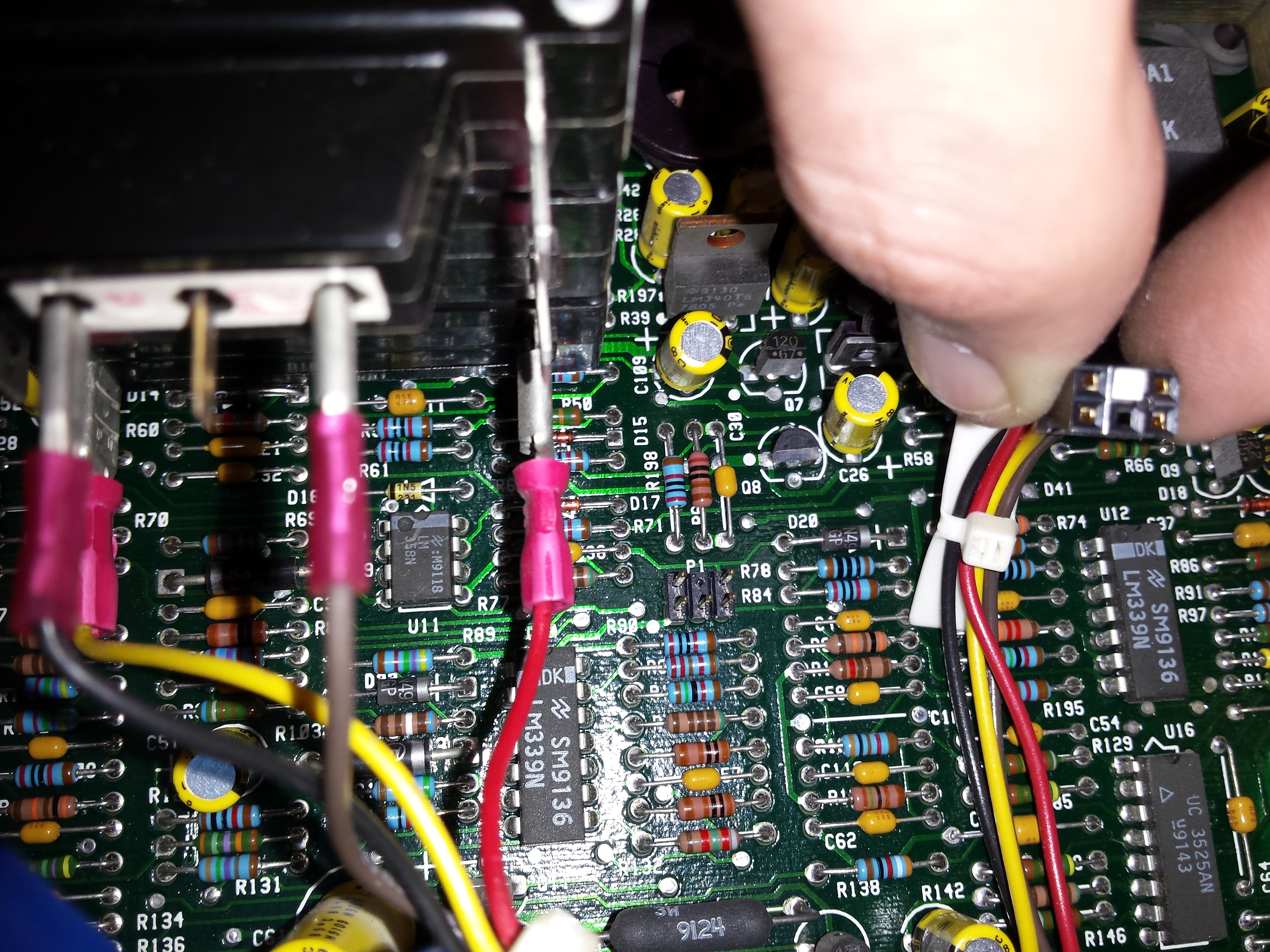 Fig. 14: Note the keying between the 6 pin female connector and the 6 pin male header (P1) on the DC board
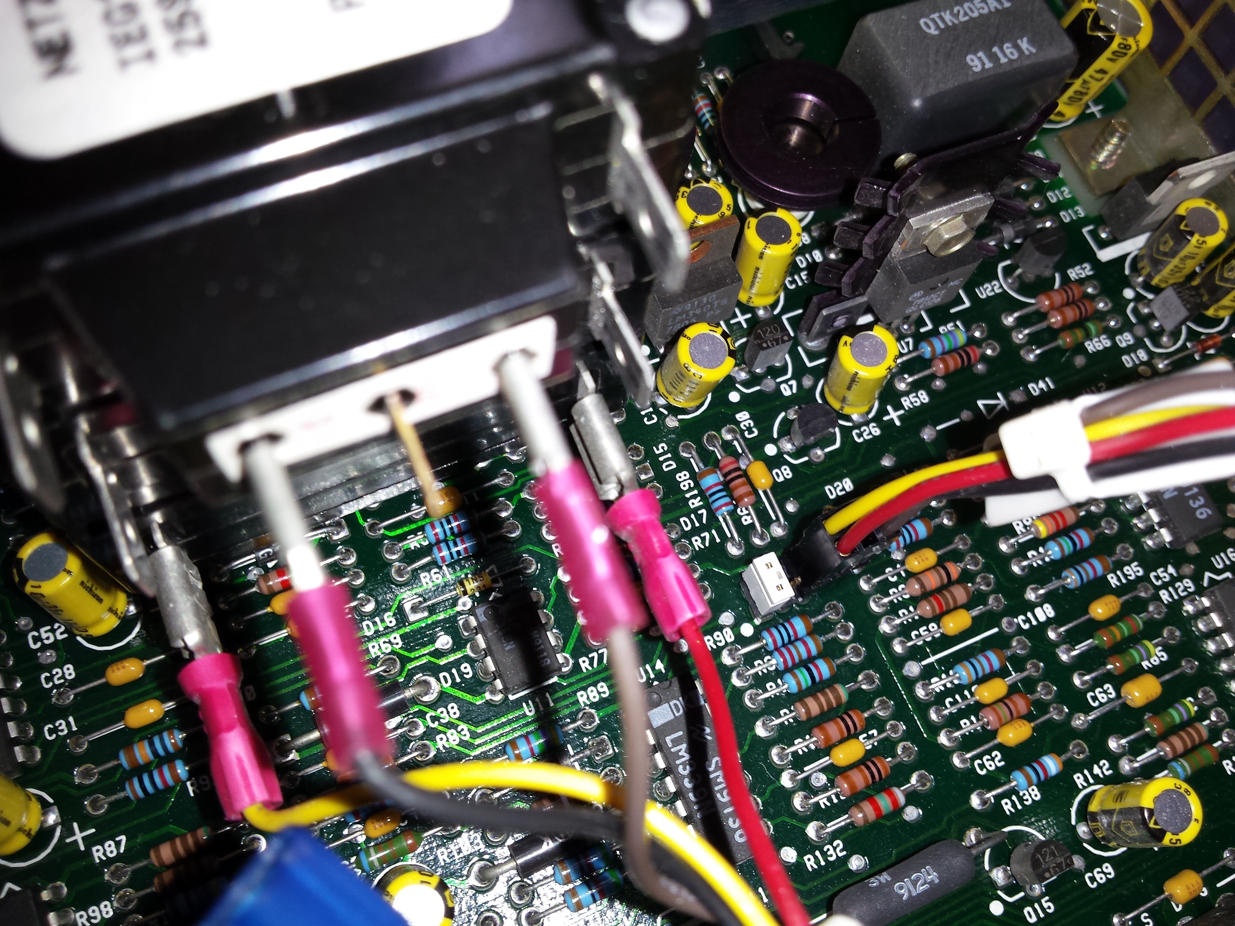 Fig. 15: 6 pin connector is rotated 180 degrees and plugged into rightmost 2 pins only, with jumper placed on
leftmost 2 pins
Fig. 15: 6 pin connector is rotated 180 degrees and plugged into rightmost 2 pins only, with jumper placed on
leftmost 2 pins
Plug the two faston jumper wires into J1 and J2 near the 9 pin connector on the DC board. Then connect the other end of the wires to one pole of the breaker assembly. Refer to figures 16 and 17.
Use a cable tie to secure the faston wires, if necessary, as in figure 18.
Lastly, assemble the face plate to the power supply, as shown in figure 19.
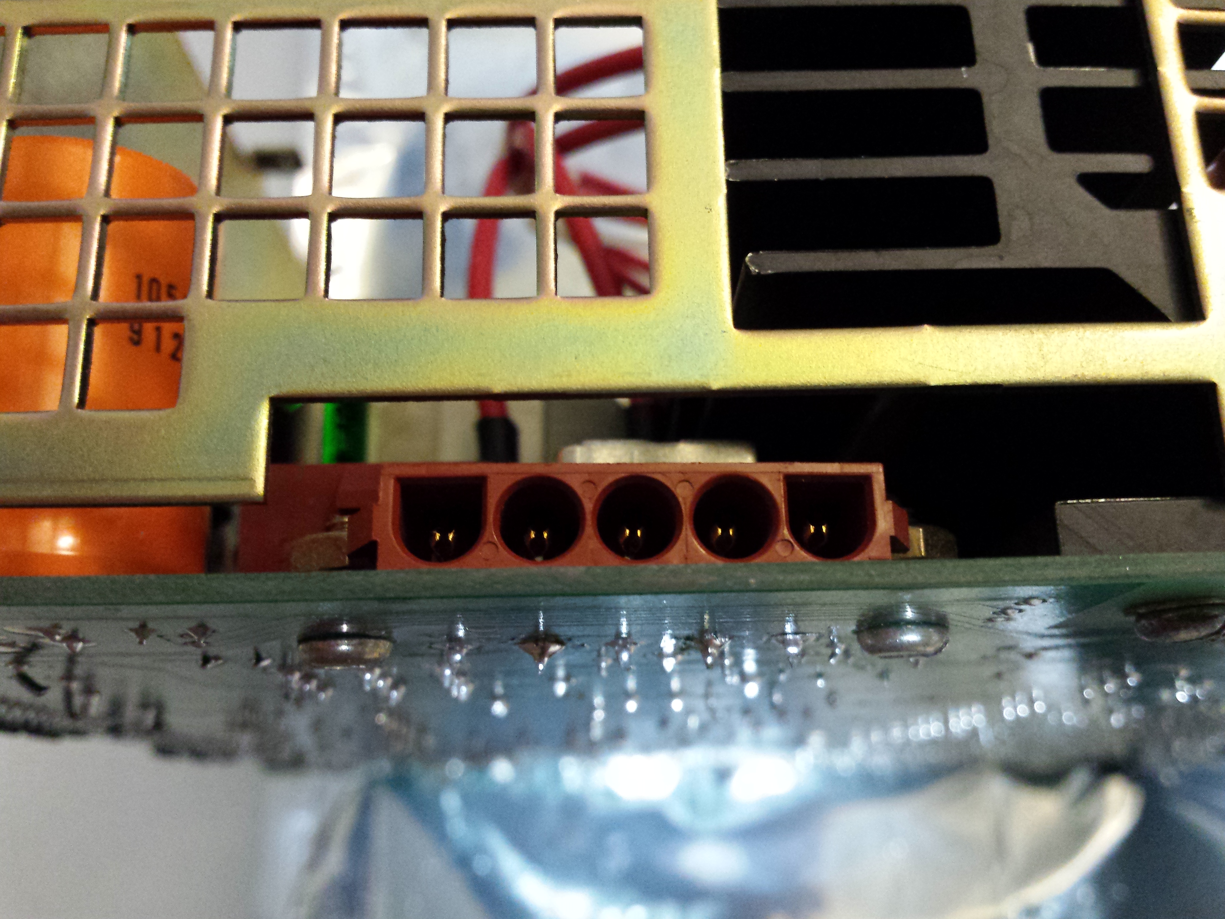
The 5 pin DC connector shown in figure 20 is used for the battery backup options on the NTAK04 and for the DC power input on the NTAK05.
Pin 1 is used on the AC model to report a fault condition when the breaker in the battery box or an NTAK28 junction box is turned off. Grounding this pin indicates a breaker that has been switched off.
Pin 2 is used for the -48V supply.
Pins 3 and 4 are used for the supply return, and are tied together in the power supply.
Pin 5 is an earth ground terminal.
Note that the supply return and earth ground should be tied together at your rectifier or a point somewhere near it (a fuse or breaker panel would also be a good place to do this, especially if you have multiple redundant rectifiers feeding your DC bus). Earth ground and the supply return wire should generally only be tied together at one point, similar to earth and neutral being bonded only at the service entrance or the output of a transformer for building AC power.
Some mating parts for this connector can be found in TE Connectivity’s MATE-N-LOK line, Kyocera’s 9090 line, and Adamtech’s DME line of connectors.