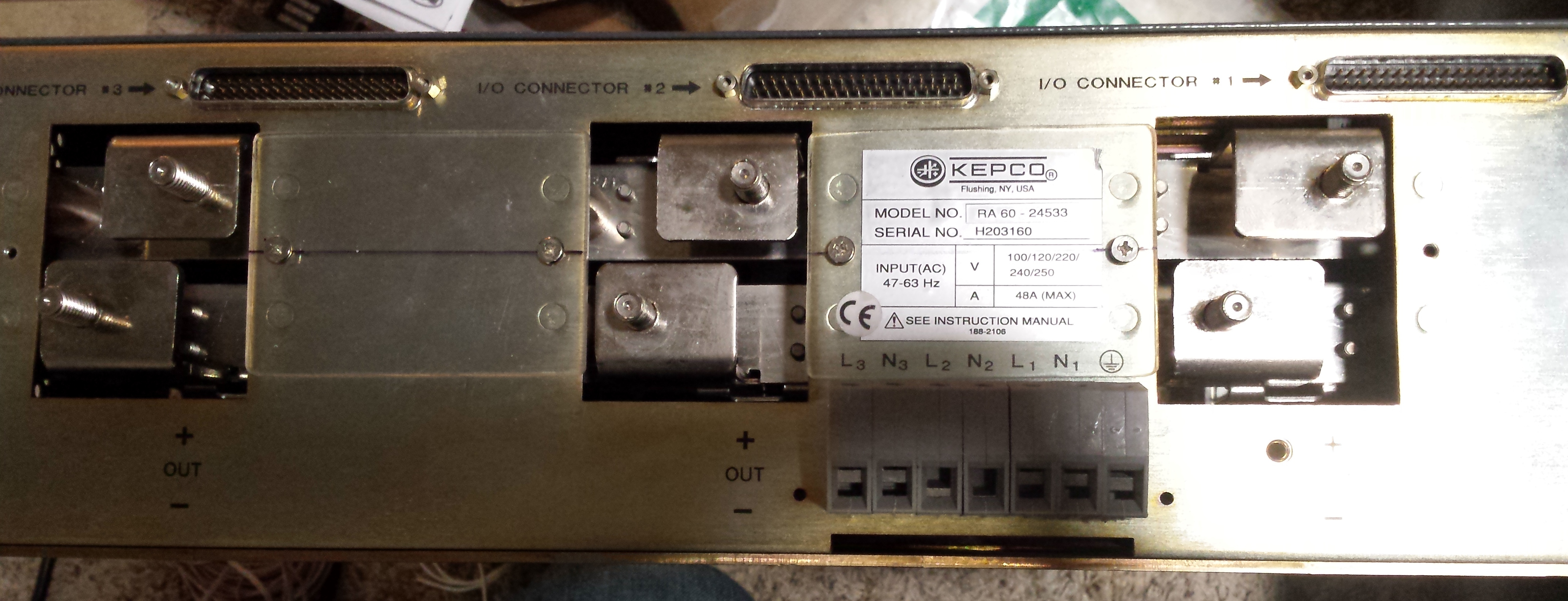
With the SL-100 equipment mostly arranged, I began to figure out power. A year or two back, I picked up a Kepco RA63 rack adapter and three matching HSP48-21R 1kW/48V/21A power supplies. There are probably better power supplies out there with less involved setup, higher efficiency, and higher power density but as an electrical engineer I liked the idea that these are extensible lab power supplies. They'll do the job here, and if I ever decide to add battery plant in the future and build some type of monitoring and control system these supplies will lend well to that given they're completely programmable by analog means via their I/O connectors.
To start to use these supplies for my DC plant, I first had to find a way to bus the outputs together. When I first purchased them, I picked up a set of crimp lugs for 4AWG wire that fit the studs on the rear of the rack adapter. I initially intended to do the bussing with wire and crimp lugs, but after thinking more about it I decided to go an alternate route.
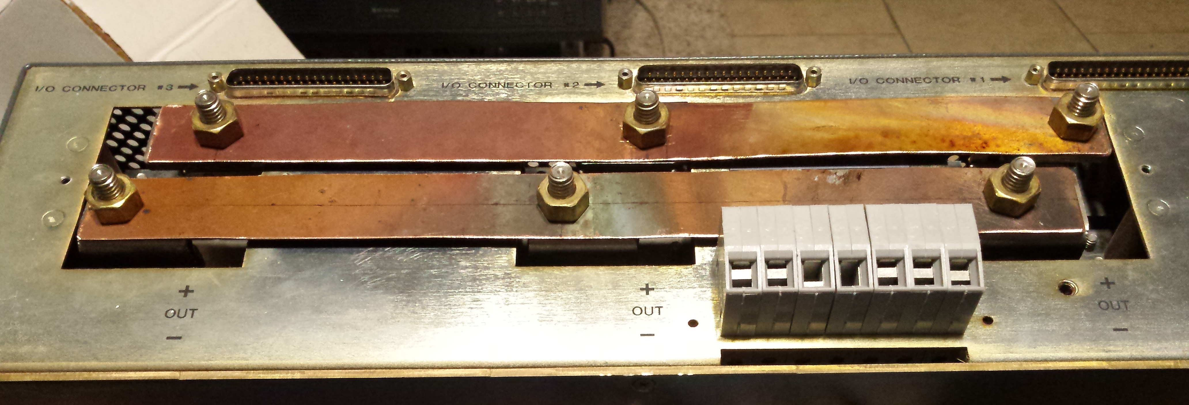
Several years ago, I found a piece of sheet copper laying on the ground outside a building and took it home. I determined a one inch wide strap would be enough copper to easily handle the current, comparing to the (cross sectionally) equivalent wire gauge on NEC ampacity charts and considering that a thin strap has better cooling than a round wire. I cut the straps and put the holes in them for the 5/16" studs, deburred them, and test fitted.
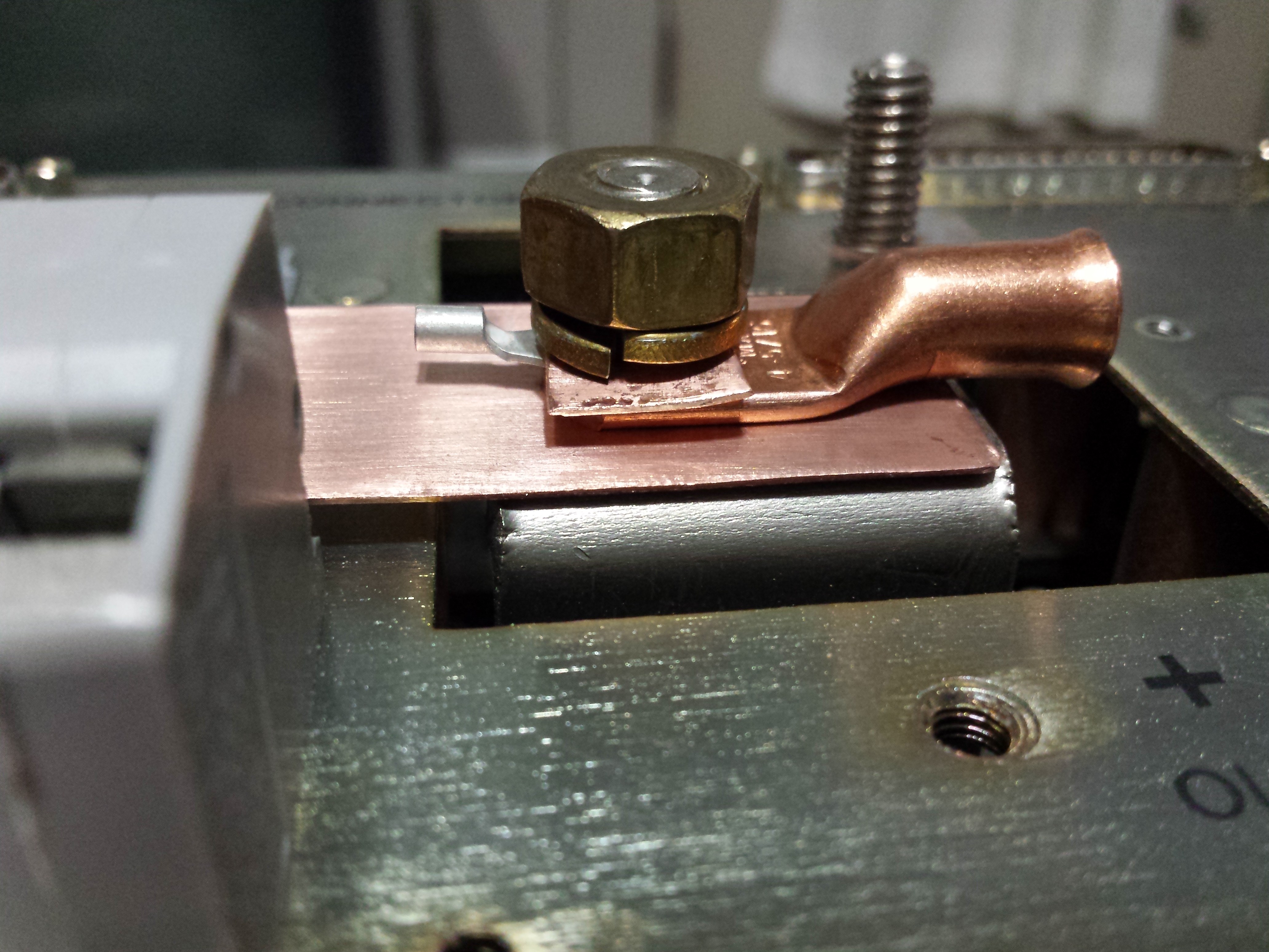
I cleaned up the oxidation on the copper with sandpaper, and test fit the hardware. I decided to add some of the scrap pieces of copper I had left over as washers to protect the lugs from the split-ring lock washers.
Next I had to make the sense wire and current sharing bus harness. The Kepco HSP line require two pins on the DC37 to be connected to the outputs for voltage sense feedback. Additionally, for current sharing between the supplies, there is a single wire used (referenced to the negative sense lead). Kepco also recommends shielding the sense lead wires if possible, and connecting the shield to the negative sense lead. Keeping in mind that in telecom, we use positive ground for the 48V power, I made sure that the shield was insulated everywhere and connected to the negative sense lead as reasonably close as I could get to the actual connection point.
With the harness made, I next addressed an issue with the bus straps: the gap from the straps to the chassis wasn't very big considering that the straps are thin copper sheet that can bend and stretch. To prevent any shorts to the chassis, I added some plastic insulation pieces between the straps and the chassis. The mounting screws for these plastic pieces were themselves close to the bus straps, so I notched the straps and bent the material away from the screws.
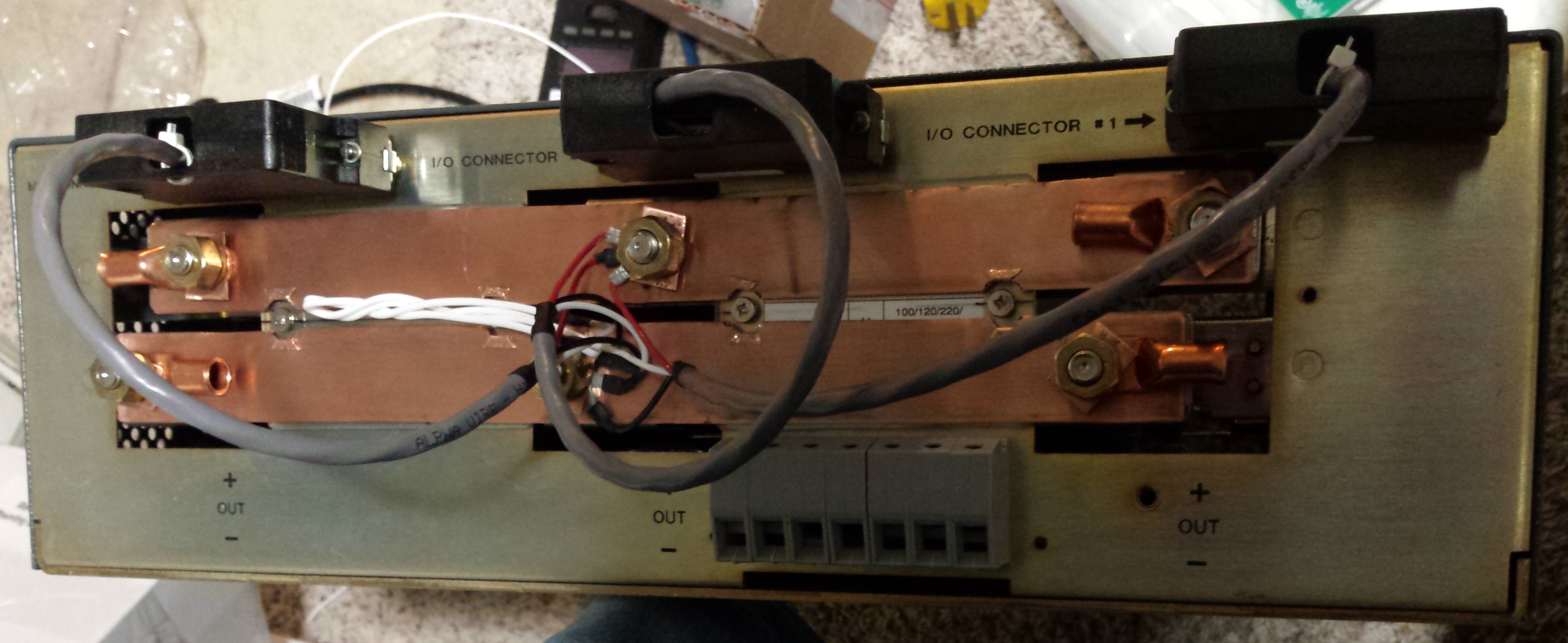
The only thing left to do was put it all together to make sure it fit right, and then test the supplies to ensure the output voltage was set correctly. At some point, I intend to add a shield of some sort over the bus straps as well to protect them from any accidental shorts. Thankfully the current limit of the supplies is only about 70A all together. I know that's a big number, but it's not wrench-melting like lead acid batteries capable of a seven hundred amps (or more) would be. Careful insulation of everything will become even more important should I ever get around to adding batteries to the system.