Now that I had the power supply set up, it was time to start working on the power wiring for the switch.
The MCAM cabinet includes a circuit breaker shelf called a BSP for power distribution. I planned to distribute power from here, but I first needed to remove the cut ends of the old wiring that went into this cabinet. There's more than just power cabling since the MCAM also contains ISM shelves which contain IOMs and MTM cards.
Then I set to work making four 4AWG cables to bring the power from the supplies into the bus bars for the BSP. I used heatshrink to help insulate part of the crimp lugs.
I installed these cables between the MCAM and the power supply, labeled them, and secured them in place with wire ties. Then I took this opportunity to power up the supplies and apply some load so I could properly set the voltage, and then test that the current sharing worked properly.
Next, I worked on clearing the old cabling out of the MCNI and the DPCC. Following that, I started to look at getting the intra-cabinet cabling reattached. The message switch cabling had me confused for a bit before I was able to piece it back together from some paper documentation I had and some pictures that had been taken prior to being disconnected.
After coming up with a makeshift cable spool rack, I started running the power cabling: First to the DPCC and MCNI cooling units (CUs), then the XA-Core, and lastly to the message switches. I had to carefully straighten some 90-degree crimp lugs for the XA-Core. I used all white wire because I had gotten a really great deal from a local online auction for it.
At this point, I had enough of the power wired to attempt booting the switch. I still had to reconstruct the DS-30 cabling that went between the message switch and the IOMs within the MCAM, but I did this off camera. I also cabled in one of the NTFX34AA RS232 adapters for the MAP VDU to see if I could get a console.
Unfortunately, try as I might, I could not get a console up on the switch. After trying a number of approaches to solving the problem, I temporarily gave up and decided to ask on some forums if anybody had a clue to what I might be doing wrong. Later that night, however, I decided to try adding more RS232 adapters to the switch and it was this which made me realize the LED on the NTFX34AA is supposed to turn GREEN when it is working.
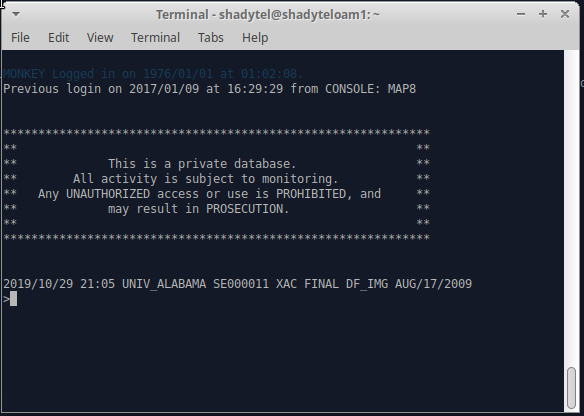
After swapping out a bad cable, I had green lights on all of the adapters. After a half hour or more waiting for the switch to finish booting, I finally got some text on the terminal and was able to login.
The timelapse video is downloadable here: 1032x774 4128x3096
All progress to date is here: 1032x774 4128x3096
The timelapses have been speed up approximately 80x. That is, one second of video corresponds to 80 seconds of real time. The 10 minutes that pass in this timelapse correspond to about 800 minutes or a nearly 13.5 hours of actual footage. The timelapse was filmed over the course of approximately two weeks.