The GE Interlogix MVC-21S is a 21" color video monitor intended for security camera monitoring applications. It appears to be a rebadged Sanyo VMC-8621P. Some additional information including a service manual can be found in the files section here.
All images on this page and more can be found in the img directory.
These monitors support PAL as well as NTSC. They have 2 composite video inputs as well as one s-video (Y/C) input. They can be modified to have an RGB+Sync input in a fairly straightforward manner.
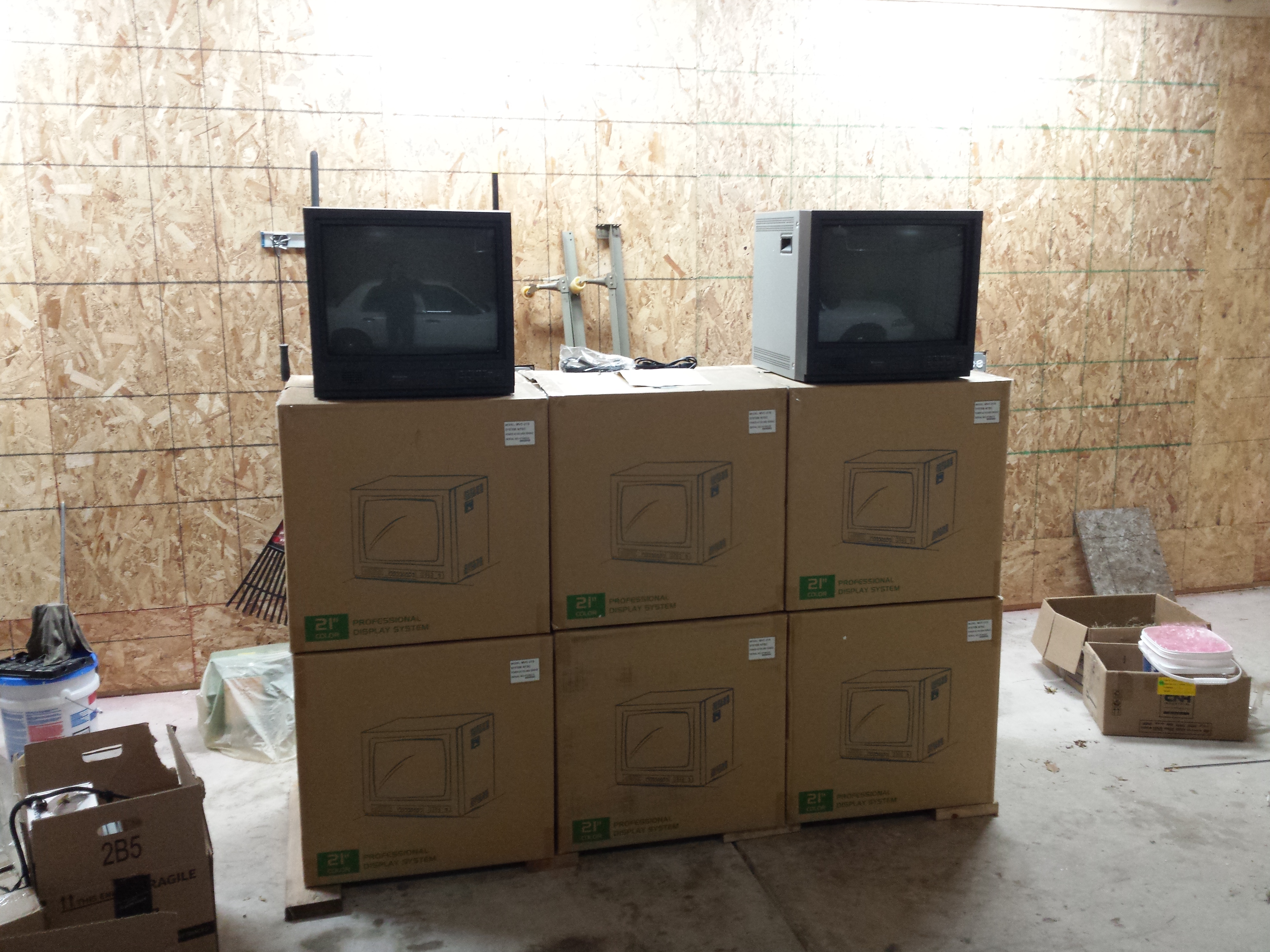
I found 8 of these 21" monitors at auction from a local school district. As far as I can tell, the school district ordered 225 monitors and these sat around as spares completely unused.
I bought them with the intention of selling during VCF MW and did so in 2021 (VCF MW 16). Some of my purchases are driven by a desire for the item itself, but often times I see a good deal that is just too good to pass up. By reselling these monitors, I passed them on to people who can get some use out of them, and they got a decent price on a like-new CRT. Frankly, there aren't too many CRTs out there with so little usage on them anymore.
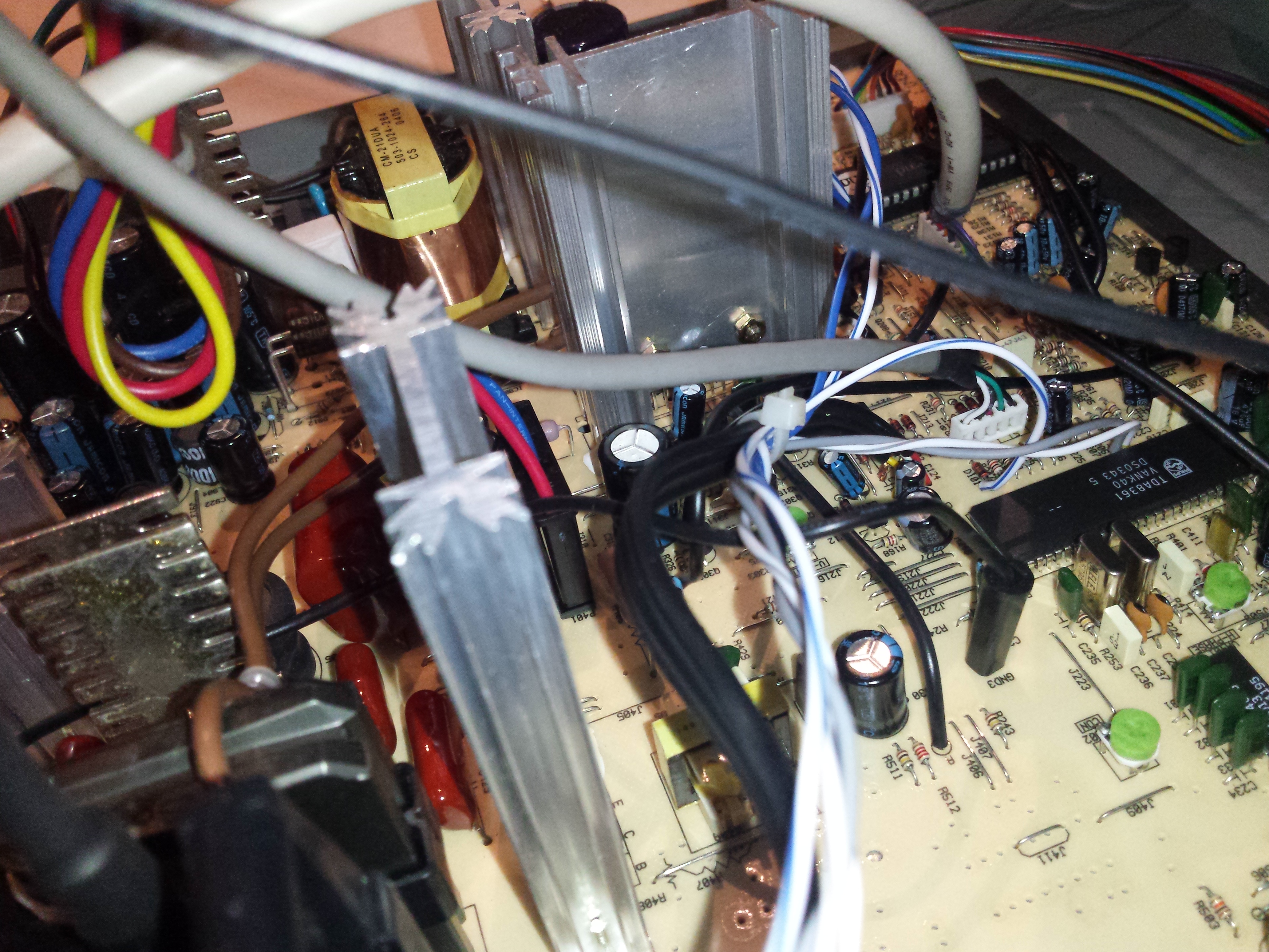
After finding the service manual for these monitors, I noticed that performing an RGB mod on them could be a relatively straightforward endeavor. Most late-model CRT monitors and TVs are implemented around a so-called TV-on-a-Chip (TVoaC). In this case, the TDA8361 was used. The TVoaC is usually a fairly universal IC, one part will often cover both NTSC and PAL standards, composite, Y/C, YPbPr, and RGB with a smattering of support chips. The RGB inputs, if present, are usually used for OSD overlays or SCART and incorporates a 'fast blank' type signal to switch to RGB with microsecond or better delays.
The TDA8361 has analog RGB inputs, and luckily they are not used for the OSD in this monitor. Often RGB input modifications will resort to breaking the displays OSD to use the RGB inputs, but that wasn't necessary in this case. I eventually got around to laying out a board for the modification after doing a rough proof of concept. The rest of this section will roughly document usage of the modification and the installation.
The PCB design files (kicad) are in the files section here.
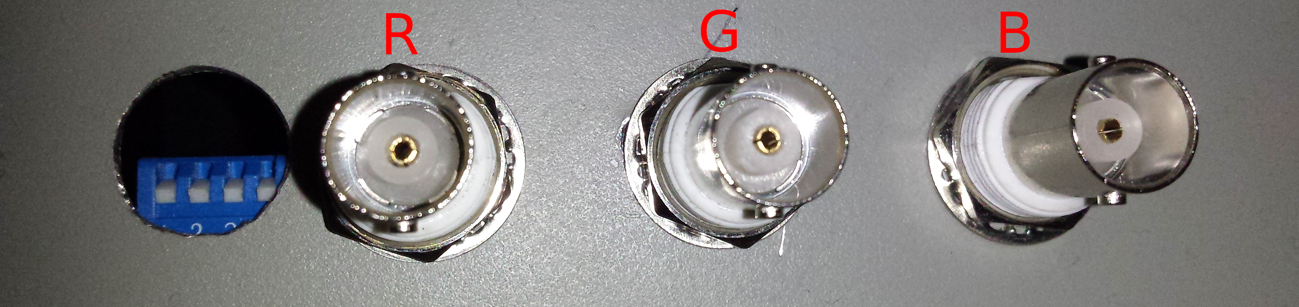
The RGB inputs are as shown below. From left to right, the ordering is dip switches, red input BNC, green input BNC, and blue input BNC.
The dip switch settings are illustrated in the following diagram:

The leftmost dip switch is used to enable or disable the RGB inputs. If the RGB inputs are enabled, then video input B is repurposed for sync input. Alternatively, the video input B will function normally as a composite input if the RGB inputs are disabled.
The rightmost dip switches enable 75 ohm termination resistors on the B, G and R inputs respectively from left to right. Normally, termination should always be enabled. However, it is possible to disable the termination and chain video out to one or more other monitors using BNC Ts. In this case, the video source should be the beginning of the chain and the farthest end of the chain should provide the termination resistance. Disabling termination resistors may also be useful to help reduce signal attenuation from weak video sources if the brightness or contrast controls are not enough alone. This can also cause issues with longer cable lengths.
A handful of different connections are possible once the RGB modification is in place, refer to this section for guidance.
In order to use video input B as a normal composite video input, simply set the dip switches according to the table above to disable the RGB inputs and connect the composite video source to the composite input.
Ensure the RGB inputs are enabled according the dip switch settings table. To connect an RGB video source with separate composite sync, connect the composite sync signal to video input B on the monitor. Additionally connect the red, green, and blue signals to the corresponding inputs on the RGB board.
Ensure the RGB inputs are enabled according the dip switch settings table. To connect a sync on green RGB video source, connect the green+sync signal to video input B on the monitor. Connect a BNC cable from video output B to the green signal BNC on the RGB board. Connect the remaining red and blue signals to their corresponding inputs on the RGB board.
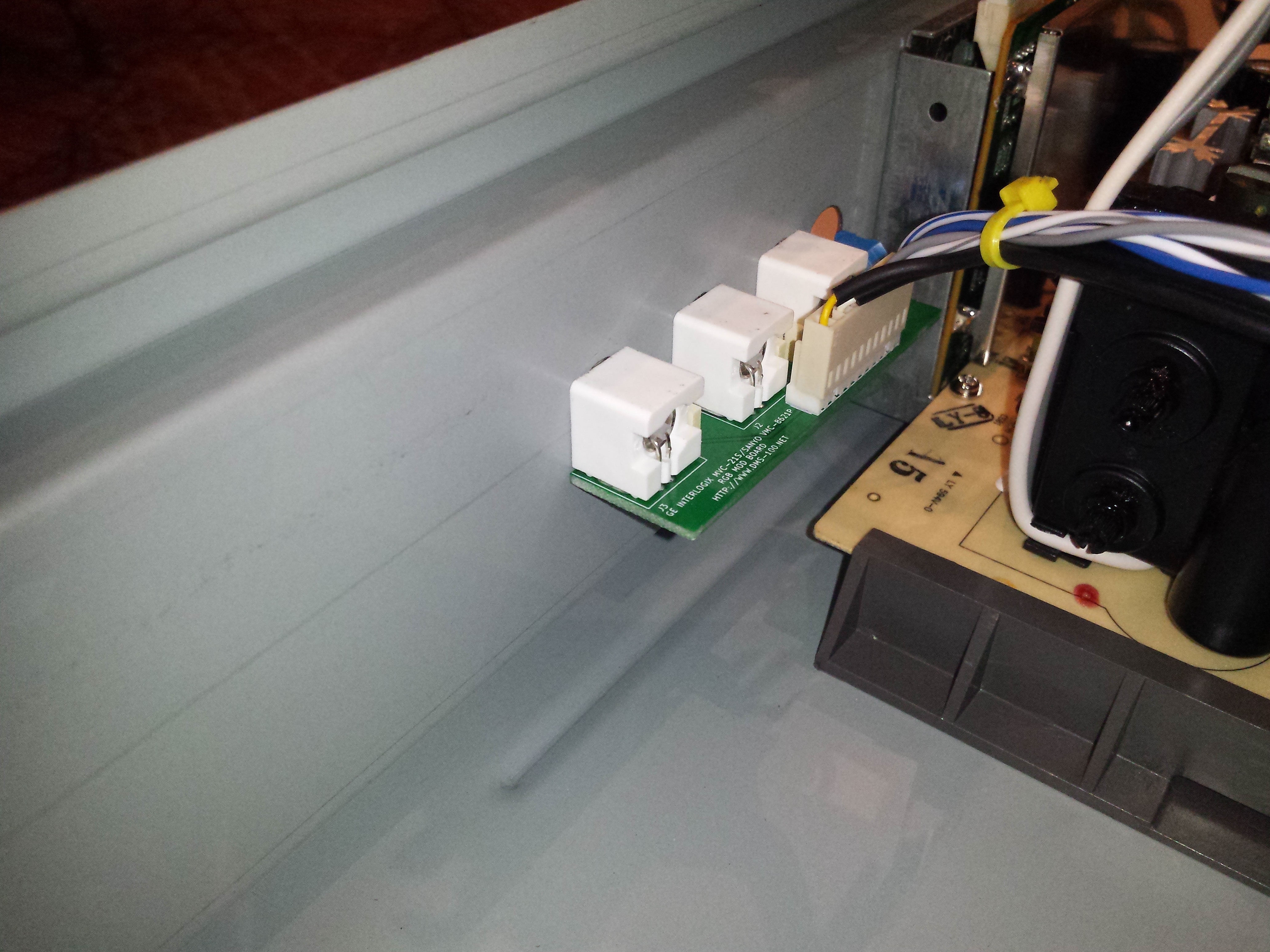
The RGB mod PCB is connected to the electronics of the monitor through an 11 pin connector, shown in the picture below. The pinout is described in the table below that.
| 1 | Blue signal |
| 2 | Blue return |
| 3 | Green signal |
| 4 | Green return |
| 5 | Red signal |
| 6 | Red return |
| 7 | +8V |
| 8 | +8V return |
| 9 | /EN2 |
| 10 | EN1 |
| 11 | FBLANK |
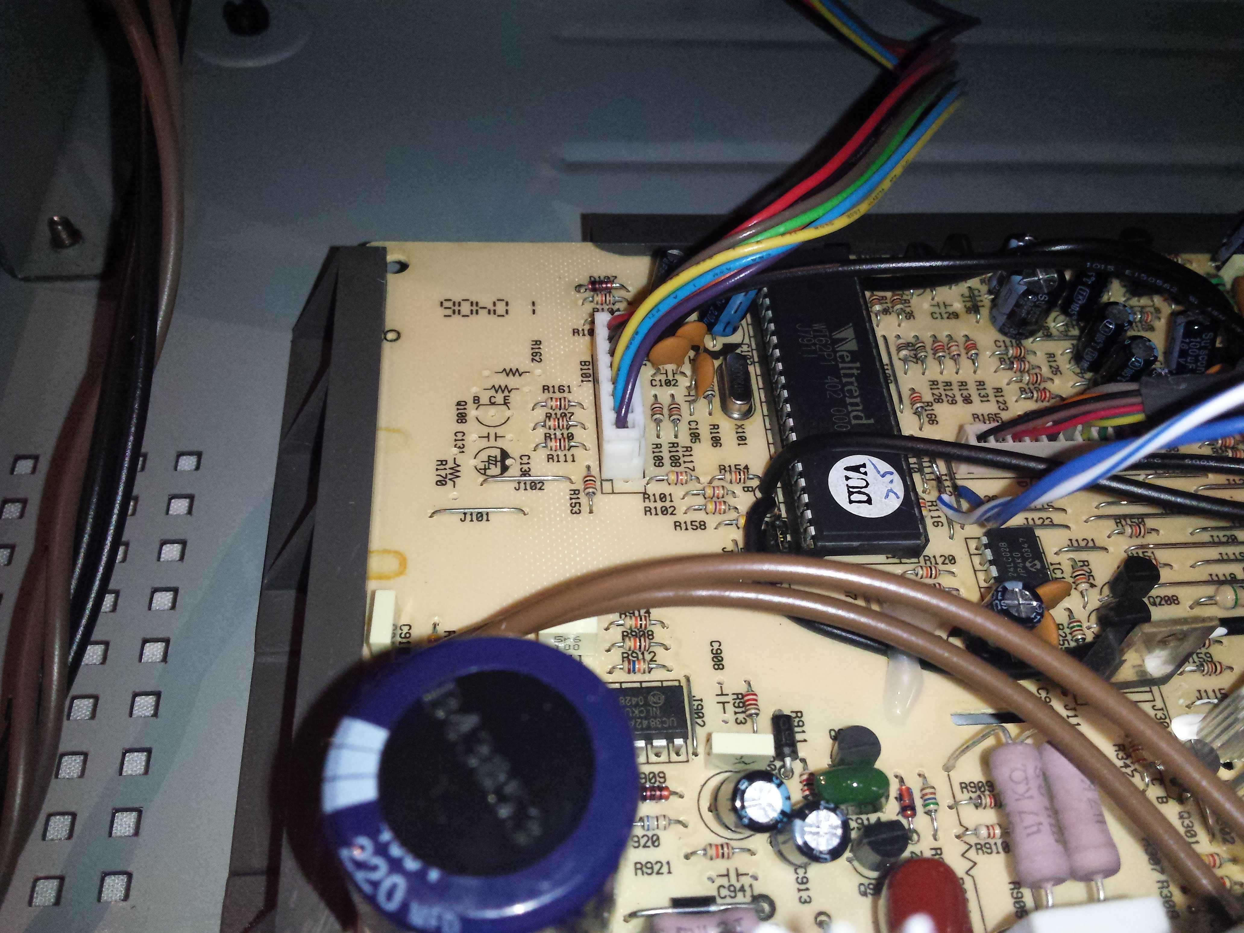
Capacitors C122, C123, and C124 (small radial film capacitors near IC202) must be removed from the monitor and transplanted into the C1, C2, and C3 positions on the RGB mod PCB. In turn, the red, green, and blue signals and returns should be wired in place of C124, C123, and C122 respectively. That is, connect red to the footprint of C124, green to C123, and blue to C122. Be sure to connect the returns to the grounded sides of these capacitor footprints (farther from IC202), and the signals to the side which connect to IC202 pins 22, 23, and 24 (closer to IC202).
Additionally, the 8V supply and return should be tapped from pins 10 and 9 on IC202 respectively. That is, pin 10 is the 8V supply and pin 9 is the return. If the polarity is flipped mistakenly, the monitor will fail to power up.
The FBLANK pin should be connected to the cathode of D101.
A jumper needs to be installed across R144, which is located near IC103.
Reference the picture below.
Pin 9, the /EN2 signal, should be connected to J111 and pin 10, the EN1 signal, should be connected to J112. These jumpers are near IC101. See the picture below for reference