This page details the VCFMW telephone network itself.
The information in this page may be updated at any time leading up to, during, or even after the show, so check back for any updates.
The network which is constructed for VCFMW offers a large number of services to subscribers and incorporates several exhibitable demonstrations of equipment and the network. The network is also a collaboration between multiple entities with Shadytel functioning as the ILEC while SneakyNet and Incompetel function as CLECs. Additionally, Rustytel is providing a demo this year.
The diagrams below show many of the physical connections in the network. You may click on the images to open them directly. They are SVGs to retain quality at large image sizes given they are dense, complex diagrams.
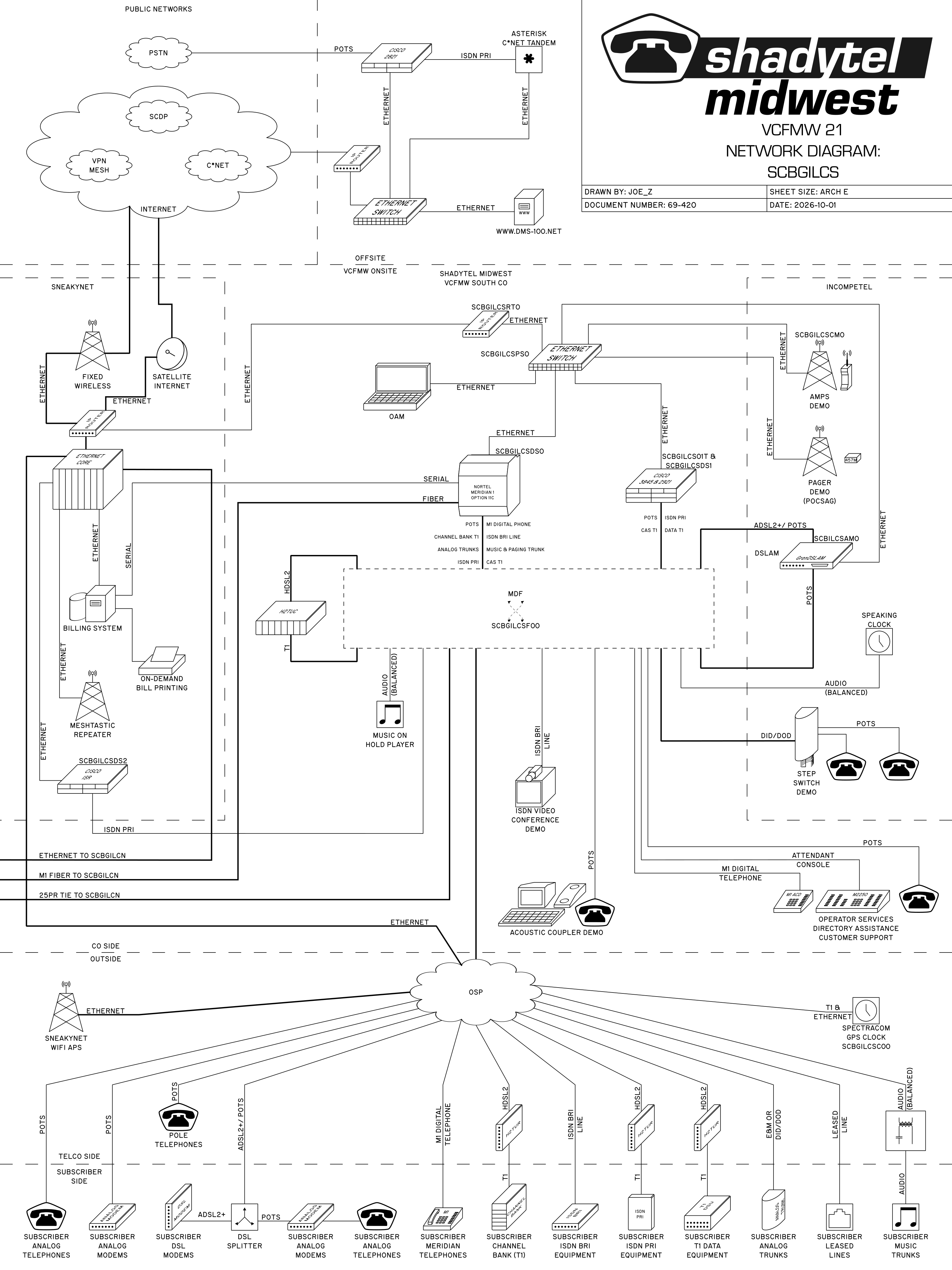
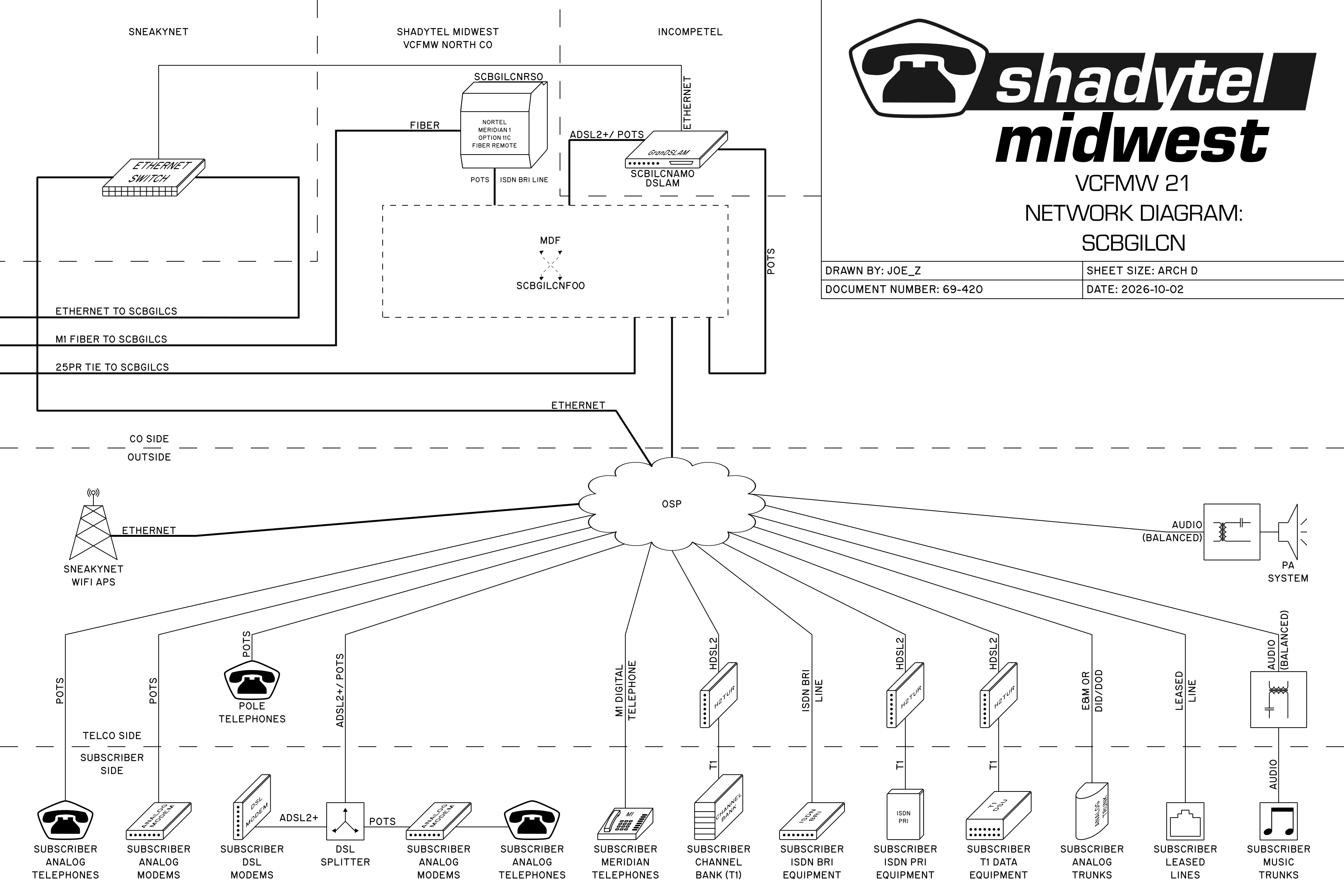
We added a remote CO this year, dividing the convention hall into the south 2/3 and the north 1/3. As such, there are two diagrams, one for the south/host CO (plus off-site equipment) and one for the north/remote CO.
South/Host CO:
North/Remote CO:
The south CO diagram can be broken into four major sections, divided by dotted lines.
The top section contains elements which are located off-site (not located on-site at VCFMW). This section is further subdivided into two sections. The first is an off-site location where other shadytel equipment is co-located. The other section is for public networks such as the internet, VoIP networks (C*NET and SCDP), and the PSTN.
The section below that area represents the Shadytel central office (CO), on-site at VCFMW in table pod C4. This section contains much of the equipment used to run the core of the network, as well as demos. It is also divided further to allow for the two other LECs, SneakyNet and Incompetel, to co-locate their network equipment and demos.
Below the CO, the outside plant (OSP) section consists of cabling, cross connection points, and other equipment located outside the CO but still part of telephone company infrastructure.
Finally, at the bottom of the diagram, the subscriber equipment is shown.
The north CO diagram is similar, but leaves out the off-site equipment which is not covered twice.
In each diagram, the various tie lines and other inter-office links are shown leaving the left side of the page to transit from one CO to the other.
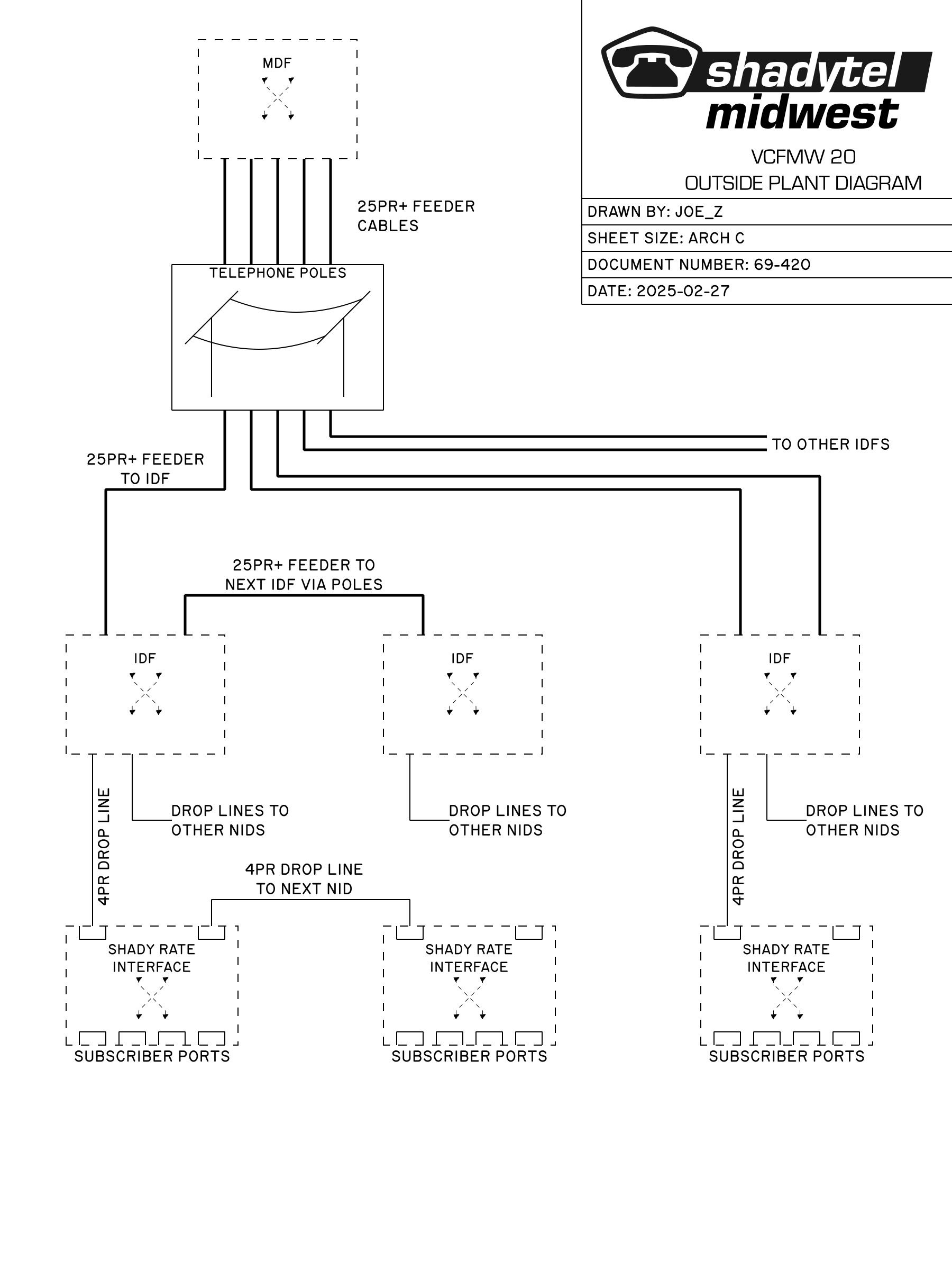
The outside plant arrangement is complex enough to warrant its own diagram, shown below. Again, you may click on the image to open it directly.
For a more detailed explanation, see the section on OSP.
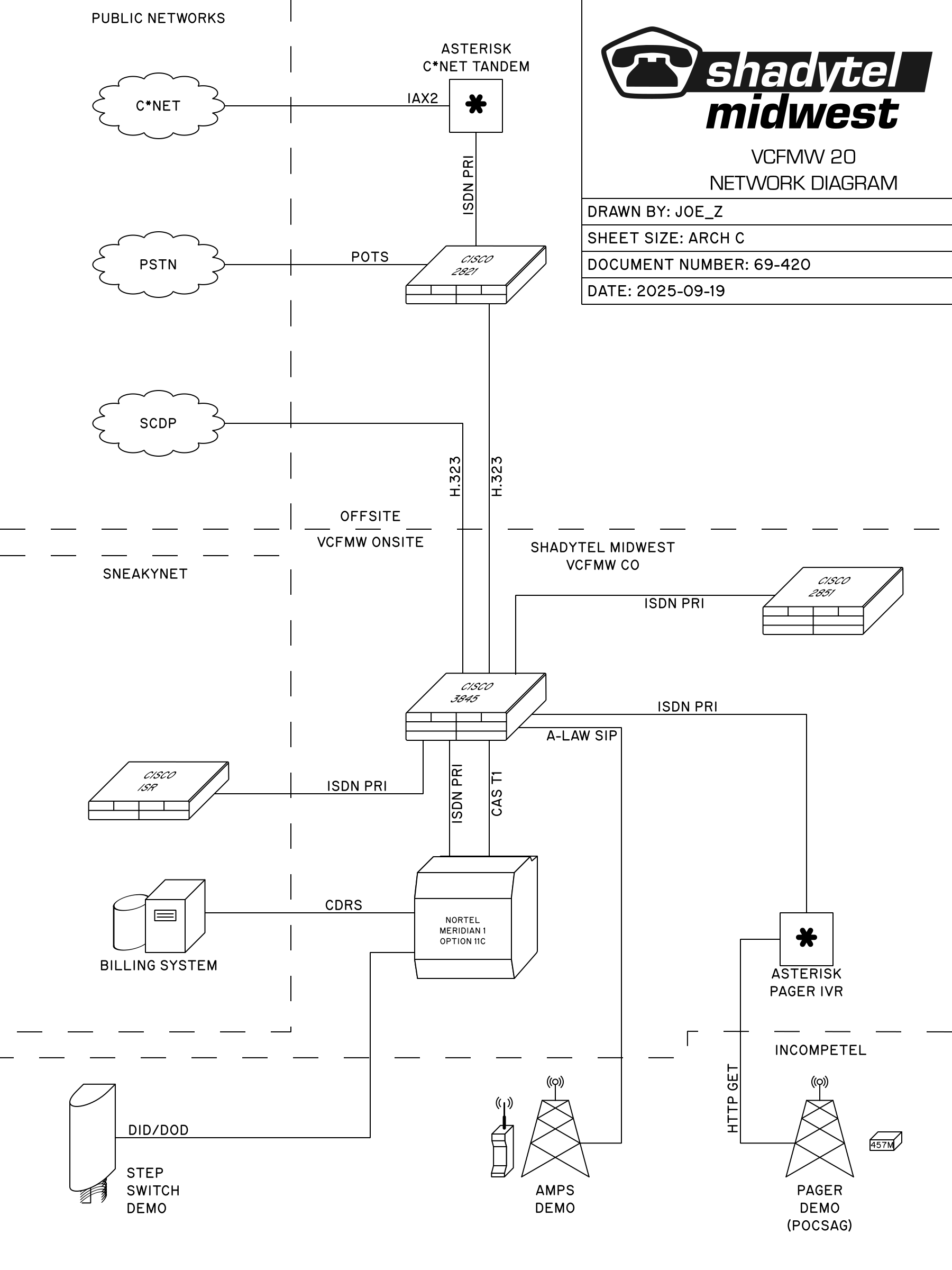
While the previous diagrams were concerned primarily with the physical connections, the last diagram is concerned with the logical trunks between the network elements.
The following sections will detail all of the pieces shown in the diagrams above and how they are connected to the other network elements.
Various demonstrations are present in the CO which are not core parts of the network but make for a good exhibit.
The step switch demo, provided by Incompetel, is a minimal standalone step switch demonstration to show how telephone switches generally worked in the late 1800s and early 1900s. The same basic technology was commonplace in North American rural areas through the mid-1980s and even persisted in some areas into the early 2000s.
The step switch provides lines to several phones for demonstration purposes. Additionally analog trunks connect it to the Meridian (through the MDF) so that calls may be placed into the step switch from the rest of the network and vice versa.
The advanced mobile phone system (AMPS) was the first widespread cellular telephone network. While this service was switched off by providers years ago, open source software exists to use SDRs to recreate the cell site equipment.
This demo, provided by Incompetel, allows cellular phones using the AMPS standard to work once again and place calls to and from the larger VCFMW network.
Because this system is based around a PC, the trunking is SIP (VoIP) running over ethernet to a Cisco 3845.
The pager demo, provided by Incompetel, allows pagers supporting the POCSAG standard and the 457.5750MHz frequency to receive pages. In order to send pages, an IVR implemented in Cisco TCL IVR scripting can be dialed or a web page using PHP can be accessed. The user enters a pager number which decodes to the capcode and type of pager (numeric or alphanumeric). Then the user can either opt to send their own ANI, or they can enter a custom callback number to be sent. The recipient of the page can then borrow a phone at an exhibit to call back whomever paged them.
The pager transmitter accepts pages over a few different IP protocols including HTTP GET requests which we opted to use for the connection between the transmitter and the IVR and web page.
In the past, we utilized an IVR on an Asterisk platform. As a matter of principal, I try to use as little Asterisk (or other soft switches) in the network as I can get away with. Aside from that, it's one less piece of hardware to bring and manage that isn't particularly interesting to look at (it's just a small form factor PC).
This demo, provided by Rustytel, demonstrates ISDN video conferencing equipment. This type of equipment was one of the use cases for ISDN BRI service, allowing two or more locations to hold a video teleconference.
These days we take this sort of service for granted with the availability of high speed internet connections in many populated areas, but once upon a time this was novel technology that slowly but surely became more and more available with advances in digital telephone services and audiovisual codec technology.
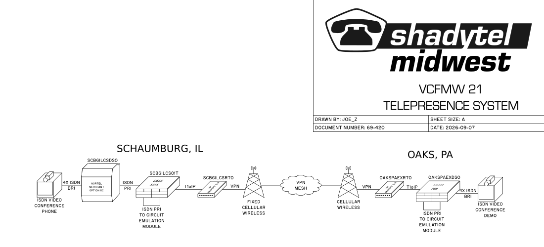
This demo uses ISDN BRI lines served from the Meridian 1.
This year, we had an off-site conference phone located at RetroCon in Oaks, PA. A regular exhibitor of VCFMW had a conflicting obligation at RetroCon and we implemented a telepresence setup using the ISDN concference phones.
Utilizing TDMoIP technology, we had intended to use ISDN data calls to connect the remote and local video conferencing equipment. This worked acceptably well in testing prior to the VCFMW. Unfortunately, the internet connection at one venue or the other was too poor for this to work correctly and we fell back to the backup plan of H323 directly between the two devices instead. This stayed up more reliably and at least transferred an image, even if the performance was not great.
Had the TDMoIP connectivity worked, the call path would have been as follows:
The Schaumburg video conferencing unit is connected to the Nortel Meridian 1 (SCBGILCSDS0) using 4 ISDN BRI lines with an aggregate bandwidth of 512kbps. 8 simultaneous data calls are carried from the Meridian 1 over an ISDN PRI link to the Cisco ISR tandem switch (SCBGILCS01T). The calls are switched to another ISDN PRI link which is connected to a circuit emulation module (CEM) capable of carrying an ISDN PRI/T1 over internet protocol (IP). This T1oIP traffic is encapsulated and carried from Schaumburg to Oaks over a virtual private network (VPN) mesh on top of the internet (a distance of over 600 miles). At the Oaks end of the link, the data is successively de-encapsulated by a VPN router and a Cisco ISR before the calls are finally switched to the video conferencing unit over 4 ISDN BRI lines.
We did succeed in an ISDN call from one conference device to another which were both located at VCFMW allowing us to at least validate the viability of local/on-site ISDN video calls.
Once upon a time, the telephone company did not allow you to connect devices to their network without their approval. Leasing a modem from the phone company was an expensive service. As a result, people devised systems that could work with the phone network without being directly connected.
Acoustic coupling was a common method used for modems during this time period. Rather than interface electrically with the telephone network, these devices interfaced acoustically with the telephone handset.
Some of these sorts of devices survived even into the era where directly connected devices were allowed. They retained some usefulness for using modems with payphones and other situations where a phone was available but not access directly to the phone line.
This demo utilizes a VT-330 terminal, a 300 bps acoustic coupler modem, a model 500 telephone set, and an analog phone line served from the Meridian 1. A Cisco 3845 with MICA modems provides the far end of the modem connection.
A guest book voicemail box is available to dial, served from the Callpilot voicemail system hosted on the Meridian 1. Additionally, several fun announcements and audio clips are hosted on the Cisco 3845 which can be dialed. An automatic number announcement service is also provided from the Cisco 3845, which can be dialed to obtain the telephone number of the calling telephone.
A speaking clock is wired into a music on hold trunk on the Meridian 1 so that any number of callers can dial a number to receive the time.
The music trunks on the Meridian can be configured such that an unlimited number of callers can dial the trunk access code to listen to the trunk making this an ideal trunk type for listen-only audio that needs to support a large number of callers.
A general description of the subscriber services are given on the Telephone Service Ordering Information page. These sections will detail how those services are connected into the larger network.
Subscriber analog telephones and modems are supplied with POTS service generally originating from the Meridian 1. The service is delivered on a basic wire pair.
ADSL2+ is delivered to the subscriber over a normal wire pair. The service is supplied from DSLAMs operated by Incompetel and located in the Shadytel COs.
This year, PPPoE is being used, provided from the Cisco 3845 ISR. Static IPs were a new offering this year, allowing services to be served from exhibits to the wider show LAN without worry of unstable IPs.
If POTS service is ordered by the same subscriber, the POTS service is delivered over the same pair as the ADSL and split out using a DSL splitter at the subscriber's table. At the DSLAM end, the POTS line needs to be cross connected into the DSLAM in order to combine the POTS and DSL service.
Meridian digital telephone service is delivered over a basic wire pair from the Meridian 1.
Subscribers may order a channel bank line served from the Meridian 1. This service is delivered as a CAS T1 using loopstart signaling. Each channel will function the same as a normal analog POTS line served from the Meridian 1.
The T1 interface is presented from an H2TUR device, supplied by the telephone company. The network side of the H2TUR uses HDSL2 for delivering the T1. That HDSL2 is supplied from H2TUC carrier equipment located in the CO, which must be cross connected to the equipment providing the T1.
ISDN BRI is delivered from the Meridian 1 over a basic wire pair.
ISDN PRI is served from a Cisco 2921. This service is delivered as a T1 trunk using ISDN signaling.
The T1 interface is presented from an H2TUR device, supplied by the telephone company. The network side of the H2TUR uses HDSL2 for delivering the T1. That HDSL2 is supplied from H2TUC carrier equipment located in the CO, which must be cross connected to the equipment providing the T1.
A data T1 is served from the Cisco 2921. This service is delivered as a T1 line.
The T1 interface is presented from an H2TUR device, supplied by the telephone company. The network side of the H2TUR uses HDSL2 for delivering the T1. That HDSL2 is supplied from H2TUC carrier equipment located in the CO, which must be cross connected to the equipment providing the T1.
Analog trunks are served over basic wire pairs from the Meridian 1. Depending on the service ordered, they may be DID, DOD, or E&M.
Leased lines are delivered depending on the customer requirements.
They may be delivered as a basic 'dry' wire pair.
They may also be delivered as a T1 circuit, presented from an H2TUR device, supplied by the telephone company. The network side of the H2TUR uses HDSL2 for delivering the T1. That HDSL2 is supplied from H2TUC carrier equipment located in the CO, which must be cross connected to another H2TUC card to provide the other leg of the ciruit.
A music trunk is delivered to the customer as an audio interface. That audio interface will vary depending on customer needs.
The audio interface is supplied from an audio coupler which converts the audio interface into a balanced signal, provides DC blocking and isolation, and protects the telephone company network and equipment.
Some elements of the network are located outside the CO, but not directly located at subscriber's tables.
SneakyNet is making use of the outside plant network to install Wi-Fi access points to provide internet access to exhibitors.
Ethernet over fiber is used to supply these access points with a data connection. The ethernet utilizes the outside plant facilities separate from the traditional telephony cable plant.
Access to the public address system is provided for convenience to show staff members possessing a privileged authentication code.
The interface uses an audio coupler between the PA system and a basic wire pair which carries a balanced audio signal. The audio coupler interfaces from the balanced audio signal to the native signal used by the PA system, provides DC blocking and isolation, and protects the telephone company network and equipment as well as the PA system.
A Spectracom GPS receiver and clock was placed closer to an outside door. An associated GPS antenna was located outside and the signal brought back inside using a coaxial cable. The GPS signal was utilized by an exhibitor as well as the Spectracom clock.
This Spectracom clock was then used to deliver a T1 timing signal to the Cisco 3845 (SCBGILCS01T) which provided stable and accurate clock for the entire network.
Every telephone pole was equipped with a telephone this year. These were provided as a courtesy to exhibitors and for use by telephone company staff. They could be used to dial telephone company services such as repair or to dial the VCFMW HQ tables to report issues with power, ask questions, etc.
Connectivity to the PSTN utilizing VoIP trunking was tested and validated this year. This service relied on the Cisco 2821 located off site on a stable public IP as the gateway to the SIP provider.
Connectivity to the PSTN this year and in previous years has been provided by extending a POTS line from the off-site Shadytel colocation facility to the show network. In future years, this service will no longer be available as AT&T discontinues POTS service in the area which serves the off-site Shadytel colocation facility. This makes it especially important to have working alternative methods to place calls into the PSTN.
In future years, it may be possible for exhibits to pay to access the PSTN. As outbound calls to the PSTN do cost real money, a small nominal fee may be required to activate service for the sake of covering costs.
Connectivity to the C*NET network is provided by an Asterisk tandem located at the Shadytel off-site colocation facility.
Connectivity to the SCDP network is being provided by the on-site Cisco 3845 ISR via H.323 trunking.
This section is for elements which perform some core function of the telephone or data networks, such as switching or routing.
Before going further, it is worth noting there were two COs and thus two wirecenters this year. The 'host' CO was mostly unchanged this year. The new 'remote' CO duplicated some equipment from the host CO used to provide the most common services. Where equipment was not present in the remote CO to serve a particular service, the host CO could serve that service over a 25 pair inter-office 'tie' cable instead.
By splitting the convention hall into the host and remote wirecenters hosted each from their respective CO, a great deal of cabling could be saved since the cabling between the host and remote is relatively minimal.
The Nortel Meridian 1 Option 11C PBX plays the role of the end office telephone switch. It provides most of the subscriber services such as analog lines, digital phone lines, channel bank T1 lines, ISDN BRI lines, analog trunks, and music and paging trunks.
The Meridian trunks with the step switch demo using analog trunks, and with the Cisco 3845 using an ISDN PRI trunk. A CAS T1 trunk is provided to carry a POTS line from a remote location into the Meridian over VoIP using the Cisco 3845. Call detail recording (CDR) data is provided to the SneakyNet billing system over asynchronous serial link. An ethernet connection is used for communications with the Callpilot voicemail system and for management.
Most of the connections to the Meridian are made through the MDF. The exceptions are the ethernet and serial data connections.
The Meridian spans two COs this year. SCBGILCSDS0 is the 'host' system located in the south CO, while SCBGILCNRS0 is the 'remote' system located in the north CO. The remote cabinet is connected back to the host system using multimode fiber optic cabling.
Logically, the remote cabinet is just an extension of the host. It is configured no differently than the normal expansion cabinets, which are already connected utilizing plastic fiber instead of glass.
The remote system could provide most of the services provided by the host system (with the notable exception of T1 trunks). However, due to low demand for many of the less common services, the remote cabinet was only used to serve analog POTS and ISDN BRI.
The Cisco 3845 ISR plays the role of a tandem office telephone switch. It provides a few subscriber services where needed, but primarily provides intraoffice T1 trunking and VoIP trunking.
Trunking is provided for the Meridian using ISDN PRI. A POTS line from a remote location is extended to the Meridian using VoIP and a CAS T1. ISDN PRI trunking is provided to the SneakyNet tandem (another Cisco ISR) for their telephone trunking. A SIP VoIP trunk is provided for the Incompetel AMPS demo. H.323 VoIP trunks are used for SCDP network access and trunking to a remote Shadytel colocation facility.
The 3845 also provides data and terminal services such as modems up to V.90 speed, V.110, V.120, PPP over ISDN B-channel, and data T1. PPPoE is provided for the DSL service.
Several ancillary services are provided by the 3845 as well, such as IVR services and dialable recorded announcements.
CDRs are collected on the 3845 and can be imported by the billing system over the ethernet connection.
The Cisco 2921 ISR plays the role of a T1 end office telephone switch. It provides customer ISDN PRI, data T1, and frame relay T1 circuits.
The Cisco 2921 also hosts the pager TCL IVR script.
CDRs are collected on the 2921 and can be imported by the billing system over the ethernet connection.
The SneakyNet tandem switch is a Cisco ISR used as the core telephony switch in the SneakyNet network. It is used for ISDN PRI trunking to the Shadytel network and to provide various Sneakynet services as well as Sneakynet NOC telephones.
The Cisco 2821 ISR plays the role of another tandem office telephone switch. An H.323 VoIP trunk is provided to the on-site Cisco 3845. ISDN PRI trunking is also provided to an Asterisk tandem switch used solely for access to C*NET.
The 2821 is used to extend a POTS line over H.323 to the equipment on-site at the show for PSTN access. It also acts as the gateway to SIP trunk providers for another means of PSTN access.
An Asterisk tandem switch, located off-site, is used as a bridge between the rest of the network and the C*NET network. Asterisk has many capabilities, but in this case its only role is as a bridge to IAX2 which is the only protocol supported by C*NET.
The Asterisk tandem is linked to the Cisco 2821 via ISDN PRI.
The Shadytel data network core is primarily ethernet based. The data network is used for services such as operations, administration, management, VoIP trunking, and internet access.
An ethernet switch provides the network for the Shadytel ethernet network, utilized by various Shadytel and Incompetel equipment. An ethernet router accomplishes routing and firewall functions between SneakyNet and the various Shadytel internal network domains. The router utilizes BGP for routing information exchange among SneakyNet and various Shadytel network elements.
The SneakyNet data network core is primarily ethernet based. This data network is also used for services such as operations, administration, management, and internet access.
An ethernet switch core, comprised of multiple ethernet switches, provides the network for the SneakyNet ethernet network. The ethernet router stack accomplishes routing, firewall, and NAT functions between multiple networks and network domains such as the Shadytel data network, the internet, and the various SneakyNet internal network domains. The router stack utilizes BGP for routing information exchange among Shadytel and various SneakyNet network elements.
Fiber optic ethernet links the ethernet switches in the host and remote COs.
The internet access provided by SneakyNet utilizes state-of-the-art fixed cellular wireless technology to provide high-speed internet access at a competitive rate.
The cellular equipment is linked with the SneakyNet router stack to provide access to the greater network.
The internet access provided by SneakyNet also utilizes state-of-the-art satellite internet access technology to provide high-speed internet access at a competitive rate.
The satellite equipment is linked with the SneakyNet router stack to provide access to the greater network.
The off-site Shadytel colocation facility has a similar ethernet router and switch setup providing networking, routing, and firewall functions between the internet, SneakyNet, and the various Shadytel internal network domains. The router utilizes BGP for routing information exchange among SneakyNet and various Shadytel network elements.
This section is for elements which perform ancillary functions of the telephone or data networks.
The Incompetel DSLAMs are used to provide ASDL2+ service to subscribers. One DSLAM is located in each of the north and south COs to serve each respective wirecenter.
The DSLAM is connected to the MDF to both provide DSL service to subscribers as well as combine analog telephone service with the DSL service on the same pair.
The DSLAM also connects to the Shadytel and Sneakynet ethernet networks for internet access and OAM functions.
Nortel M2250 attendant consoles are used to provide operator services for the telephone network. Nortel ACD telephone sets are used to provide directory assistance and customer support. These telephones are served from the Nortel Meridian 1.
The music on hold player is used to provide the audio source for music which plays to calls which have been placed on hold. The music player is connected to the Meridian through the MDF.
SneakyNet has been contracted to provide billing services for Shadytel. The billing system ingests call detail records from the Meridian and Cisco ISRs to produce bills for subscriber services based on usage.
The billing system uses an asynchronous serial link from the Meridian to receive call detail records. CDR files are transferred from the Cisco ISRs using Ethernet. Ethernet is also used for OAM purposes.
Rather than deliver bills to exhibitors, this year exhibitors were asked to pick up their bills from the CO. For this purpose, an on-demand bill printing system was created.
By doing things this way, we could avoid the extensive effort associated with delivering bills and save the paper from non-deliverable bills. Additionally, any exhibits who decided to leave early could pick up their bills early if they wanted.
The HDSL2 carrier equipment is used in delivery of various types of T1 circuit to subscribers. T1 equipment is cross connected to an H2TUC card through the MDF. The H2TUC is then cross connected through the MDF and the OSP to the subscriber where a telephone company owned and provided H2TUR is used to provide the T1 circuit.
Shadytel and the other LECs use a variety of OAM equipment, but primarily staff are using laptop computers connected to the data network via ethernet (and sometimes Wi-Fi or other means).
The web server for this website, located in the shadytel off-site colocation facility, is connected to the internet via ethernet. The website is used to provide information such as this web page, directory information, telephone service ordering information, and telephone service usage information.
The outside plant (OSP) arrangement is detailed in a separate diagram to show the added complexity separate from the rest of the network. The diagram is repeated here.
The main distribution frame (MDF) is a cross connection field between the various pieces of equipment in the CO and the cabling which extends outside the CO. By placing cross connection jumpers in the MDF, equipment can be appropriately connected to other equipment in the CO or to cable pairs which extend out of the office towards subscribers.
The MDF is shown in both the overall network diagram and the OSP diagram, as it functions as the interface between the CO and the OSP.
Feeder cables originate at the MDF. The cables are distributed out via the network of telephone poles and floor-level crossings to the various groups of tables which are served by those feeders. At each group of tables served by a feeder cable, there is an intermediate distribution frame (IDF). An IDF may be served by more than one feeder cable, and a feeder cable may serve more than one IDF. A feeder cable may even be one of multiple feeders serving an IDF and extend onward to serve another IDF.
The arrangement of feeders is dependent on the subscriber service density being served in each table group.
An intermediate distribution frame (IDF) is a cross connection field between feeder cables and subscriber drop lines. By making connections in the IDF, feeder cable pairs and subscriber drop lines can be appropriately connected to deliver services to subscribers.
In general, one IDF will be present for each table group which receives service. An IDF may be fed from one or more feeder cables, and those feeder cables may optionally continue onward to other IDFs.
Drop lines originate in an IDF and connect to one or more shady rate interface devices. The drop lines will contain multiple pairs and thus may be shared among more than one subscriber depending on density of service.
The shady rate interfaces (SRIs) act as a robust network interface device (NID) which is the demarcation point between the subscriber and network.
Each SRI accepts a four pair drop line which may be optionally passed through to other SRIs in the same chain. Generally, up to four SRIs may be used on a single drop line.
On the subscriber side, the SRI provides up to 4 ports for the services being delivered. In some instances, telephone company owned and provided equipment will be connected to these ports, such as H2TUR or audio coupler devices. In those cases, the telephone company owned equipment will be considered an extension of the network and will provide its own customer interface downstream of the SRI.